Maverick and Comet Repair
Fuel System
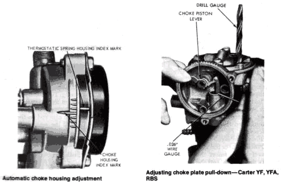
AUTOMATIC CHOKE HOUSING ADJUSTMENT
Carter YF, YFA,
RBS, Autolite (Motorcraft) 2100D And 2150
By rotating
the spring housing of the automatic choke, the reaction of the choke
to engine temperature can be controlled. To adjust, remove the air
cleaner assembly, loosen the thermostatic spring housing retaining
screws and set the spring housing to the specified index mark. The
marks are shown in the accompanying illustration. After adjusting
the setting, tighten the retaining screws and replace the air
cleaner assembly to the carburetor.
CHOKE PLATE PULL-DOWN CLEARANCE
Carter
YF, YFA, And RBS
- Remove the carburetor air cleaner, and remove the choke thermostatic spring housing.
- Bend a section of 0.026 in. diameter wire at a 90° angle approximately 1/8 in. from one end.
- Insert the bent end of the wire gauge between the choke piston slot and the righthand slot in the choke housing. Rotate the choke piston lever counterclockwise until the gauge is snug in the piston slot.
- Exert light pressure upon the choke piston lever to hold the gauge in position. Check the specified clearance with a drill of the correct diameter between the lower edge of the choke plate and the carburetor bore.
- Choke plate pull-down clearance may be adjusted by bending the choke piston lever as required to obtain the desired clearance. It is recommended the choke piston lever be removed prior to bending, in order to prevent distorting the piston link.
- Install the choke thermostatic spring housing and gasket, and set the housing to the proper specification.
Autolite (Motorcraft) 21 ODD
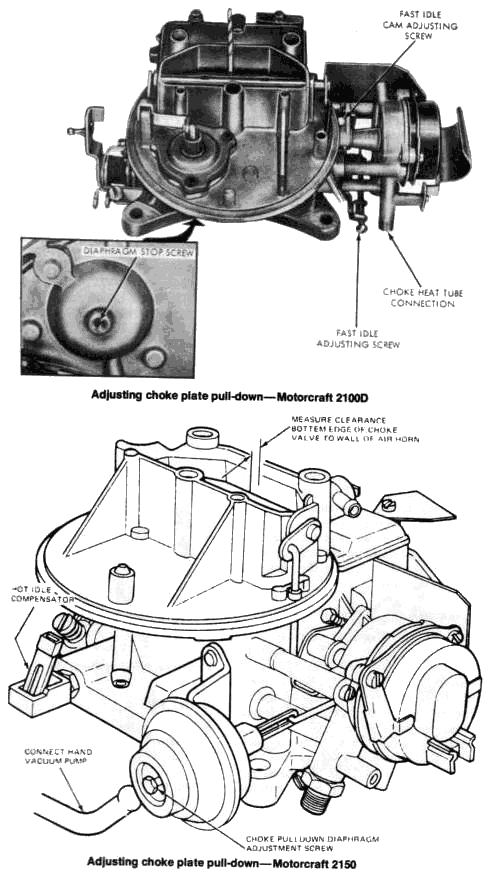
- Remove the air cleaner.
- With the engine at its normal operating temperature, loosen the choke thermostatic spring housing retaining screws, and set the housing 90° in the rich direction.
- Disconnect and remove the choke heat tube from the choke housing.
- Turn the fast idle adjusting screw outward one full turn.
- Start the engine. Use a drill of the specified diameter to check the clearance between the lower edge of the choke plate and the air horn wall.
- To adjust the clearance, turn the diaphragm stopscrew (located on the underside of the choke diaphragm housing). Turning clockwise will decrease the clearance; counterclockwise will increase it.
- Connect the choke heat tube, and set the choke thermostatic spring housing to the proper specification. Adjust the fast idle speed to specifications.
Motorcraft 2150
- Remove the air cleaner assembly.
- Set the throttle on the top step of the fast idle cam.
- Noting the position of the choke housing cap, loosen the retaining screws and rotate the cap 90 degrees in the rich (closing) direction.
- Activate the pull-down motor by manually forcing the pull-down control diaphragm link in the direction of applied vacuum or by applying vacuum to the external vacuum tube.
- Using a drill gauge of the specified diameter, measure the clearance between the choke plate and the center of the air horn wall nearest the fuel bowl.
- To adjust, reset the diaphragm stop on the end of the choke pull-down diaphragm.
- After adjusting, reset the choke housing cap to the specified notch. Check and reset fast idle speed, if necessary. Install the air cleaner.
FLOAT LEVEL ADJUSTMENT
CARTER YF, YFA
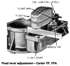
The float level is adjusted dry in the following manner: Remove the
carburetor air horn and gasket from the carburetor. Using a gauge
made to the proper dimension, invert the air horn assembly and check
the clearance between the top of the float and the bottom of the air
horn. Float level is 7/36 in. for 1970 models equipped with the 170
six and 3/8 in. for all other 1970-77 models. When checking the
float level, the air horn should be resting on the pin of the needle
valve. The float lever arm may be bent in order to adjust the float
clearance. However, do not bend the tab at the end of the float arm,
as this will prevent the float from bottoming in the fuel bowl when
the bowl is empty. Using a new gasket, install the carburetor air
horn.
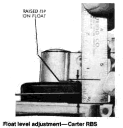
Carter RBS
Remove the fuel
bowl and gasket and invert the main body. With only the weight of
the float assembly pressing against the needle and seat, measure the
vertical distance between the main body casting and the raised tips
in the outer ends of the float as shown in the accompanying
illustration.
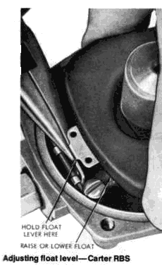
NOTE: The measurement should be made at both ends of the float, and should be 9/16 in.
If necessary, the measurements may be equalized by holding the float lever as shown and twisting the float as required. When the float level is being adjusted, hold the tab of the float lever away from the needle valve.
Autolite (Motorcraft)
2100D, 2150
DRY ADJUSTMENT
This preliminary setting
of the float level adjustment must be done with the carburetor
removed from the engine.
- Remove the air horn and see that the float is raised and the fuel inlet needle is seated. Check the distance between the top surface of the main body (with the gasket removed) and the top surface of the float. Depress the float tab to seat the fuel inlet needle. Take a measurement near the center of the float, at a point 1/8 in. from the free end. If you are using a prefabricated float gauge, place the gauge in the corner of the enlarged end section of the fuel bowl. The gauge should touch the float near the end, but not on the end radius.
- If necessary, bend the tab on the end of the float to bring the setting within the specified limits.
WET ADJUSTMENT
- Bring the engine to its normal operating temperature, park the car on as nearly level a surface as possible, and stop the engine.
- Remove the air cleaner assembly from the carburetor.
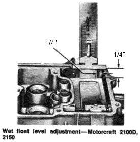
- Remove the air horn retaining screws and the carburetor identification tag. Leave the air horn and gasket in position on the carburetor main body. Start the engine, let it idle for several minutes, rotate the air horn out of the way, and remove the gasket to provide access to the float assembly.
- With the engine idling, use a standard depth scale to measure the vertical distance from the top machined surface of the carburetor main body to the level of the fuel in the fuel bowl. This measurement must be made at least 1/4 in. away from any vertical surface in order to assure an accurate reading.
- Stop the engine before making any adjustment to the float level. Adjustment is accomplished by bending the float tab (which contacts the fuel inlet valve) up or down as required to raise or lower the fuel level. After making an adjustment, start the engine, and allow it to idle for several minutes before repeating the fuel level check. Repeat as necessary until the proper fuel level is attained.
- Reinstall the air horn with a new gasket and secure it with the screws. Include the installation of the identification tag in its proper location.
- Check the idle speed, fuel mixture, and dashpot adjustments. Install the air cleaner assembly.
METERING ROD
ADJUSTMENT
Carter YF, YFA
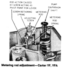
With the carburetor air
horn and gasket removed from the carburetor, unscrew the idle speed
adjusting screw until the throttle plate is tightly closed in the
throttle bore. Press downward on the end of the diaphragm shaft
until the metering rod arm contacts the lifter link at the diaphragm
stem. With the metering rod in the preceding position, turn the rod
adjustment screw (see accompanying illustration) until the metering
rod just bottoms in the body casting. Turn the metering rod
adjusting screw one additional turn in the clockwise direction.
Install the carburetor air horn along with a new gasket.
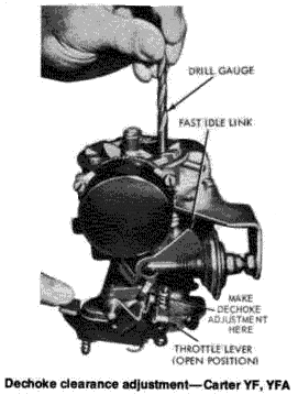
DECHOKE CLEARANCE
ADJUSTMENT
Carter YF, YFA
- Remove the carburetor air cleaner.
- Hold the throttle plate to the full open position while closing the choke plate as far as possible without forcing it. Use a drill of the proper diameter (see Specifications) to check the clearance between the choke plate and air horn.
Carter RBS
The procedure for doing this on the Carter YF carburetor also
applies to this type, except that the adjustment is accomplished by
bending the tang on the throttle lever.
ACCELERATOR PUMP
STROKE ADJUSTMENT
Carter RBS
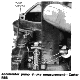
Unscrew the idle
speed adjusting screw and open the choke plate so that the
throttle plate is seated in its bore. Measure the distance
between the flat surface of the main body casting and the top
surface of the accelerating pump stem, as shown in the
accompanying lustration. With the throttle in the wide-open
position, measure the height again. The pump stroke is the
difference between the first measurement and the second, and
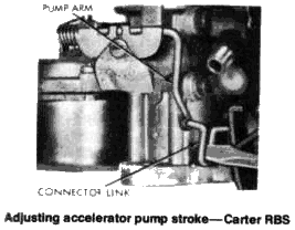
should be .400 in. The pump stroke may be adjusted by opening or
closing the pump connector link at the offset portion as shown.
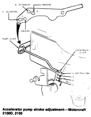
Autolite (Motorcraft) 2100D, 21500,2150
In order to keep the
exhaust emission level of the engine within the specified
limits, the accelerating pump stroke has been preset at the
factory. The additional holes are provided for differing
engine-transmission-body applications only. The primary throttle
shaft lever (over-travel lever) has 4 holes and the accelerating
pump link 2 holes to control the pump stroke. The accelerating
pump operating rod should be in the over-travel lever hole
number listed in the "Carburetor Adjustments" specifications
table, and in the inboard hole (hole closest to the pump
plunger) in the accelerating pump link. If the pump stroke has
been changed from the specified settings, use the following
procedure to correct the stroke.
- Release the operating rod from the retaining clip by pressing the tab end of the clip toward the rod while pressing the rod away from the clip until it disengages.
- Position the clip over the specified hole (see "Carburetor Adjustments" specifications table) in the over-travel lever. Press the ends of the clip together and insert the operating rod through the clip and the over-travel lever. Release the clip to engage the rod.
