Maverick and Comet Repair
Engine Electrical
ENGINE ELECTRICAL
Ignition System
Two types of ignition systems are utilized in Mavericks and Comets.
A conventional ignition system using breaker points and condenser is
used on all 1970-73 models and most 1974 models sold outside the
state of California. A breakerless solid-state1 ignition system
using an armature and magnetic pickup coil assembly in the
distributor and a solid-state amplifier module inline between the
coil and the distributor is installed in all 1974 Mavericks and
Comets sold in the state of California, and installed in all 1975-77
models sold nationwide.
In 1977, an improved system with greater spark output was introduced: This system is known as Dura Spark and can be identified by the larger diameter distributor cap and larger (from 7mm to 8mm) plug wires. The Dura Spark system utilizes higher voltages up to 42,000 volts to allow wider spark plug gaps necessary to fire leaner fuel/air mixtures.
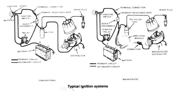
Both systems employ a distributor which is driven by the camshaft at one-half crankshaft rpm, high-voltage rotor, distributor cap and spark plug wiring, and an oil-filled conventional type coil.
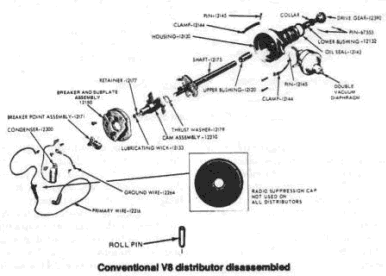
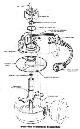
The two systems differ in the manner in which they convert electrical primary voltage (12 volts) from the battery into secondary voltage (at least 20,000 volts) to fire the spark plugs. In the conventional system, the breaker points open and close as the moveable breaker arm rides the rotating distributor cam eccentric, thereby opening and closing the current to the coil. When the points open, they interrupt the flow of primary current to the coil, causing a collapse of the magnetic field in the coil and creating a high tension spark which is used to fire the sparkplugs. In the breakerless system, a distributor shaft-mounted armature rotates past a magnetic pickup coil assembly causing fluctuations in the magnetic field generated by the pickup coil. These fluctuations in turn, cause the amplifier module to turn the ignition coil current off and on, creating the high tension spark to fire the spark plugs. The amplifier module electronically controls the dwell, which is controlled mechanically in a conventional system by the duration that the points remain closed.
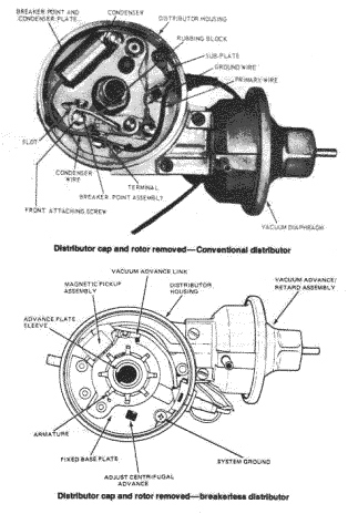
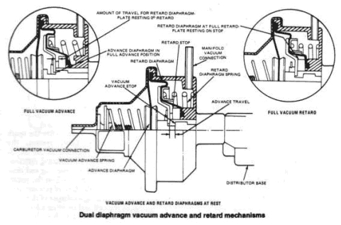
Both the conventional and breakerless ignition systems are equipped with dual advance distributors. The vacuum advance unit governs ignition timing according to engine load, while the centrifugal advance unit governs ignition timing according to engine rpm. Centrifugal advance is controlled by spring mounted weights contained in the distributor, located under the breaker point mounting plate on conventional systems and under the fixed base plate on breakerless systems. As engine speed increases, centrifugal force moves the weights outward from the distributor shaft advancing the position of the distributor cam (conventional) or armature (breakerless), thereby advancing the ignition timing. Vacuum advance is controlled by a vacuum diaphragm which is mounted on the side of the distributor and attached to the breaker point mounting plate (conventional) or the magnetic pickup coil assembly (breakerless) via the vacuum advance link. Under light acceleration, the engine is operating under a low-load condition, causing the carburetor vacuum to act on the distributor vacuum diaphragm, moving the breaker point mounting plate (conventional) or pickup coil assembly (breakerless) opposite the direction of distributor shaft rotation, thereby advancing the ignition timing.
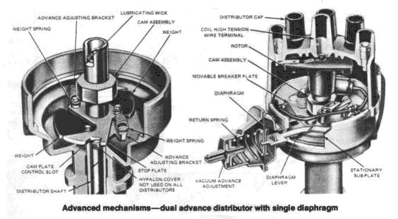
The distributors on many models also incorporate a vacuum retard mechanism. The retard mechanism is contained in the rear of the vacuum diaphragm chamber. When the engine is operating under high-vacuum conditions (deceleration or idle), intake manifold vacuum is applied to the retard mechanism. The retard mechanism moves the breaker points mounting plate (conventional) or pickup coil assembly (breakerless) in the direction of distributor rotation, thereby retarding the ignition timing. Ignition retard, under these conditions, reduces exhaust emissions of hydrocarbons, although it does reduce engine efficiency somewhat.
Distributor
REMOVAL AND INSTALLATION
- On 302 V8 models, remove the air cleaner.
- On models equipped with a conventional ignition system, disconnect the primary wire at the coil. On models equipped with breakerless ignition, disconnect the distributor wiring connector from the vehicle wiring harness.
- Noting the position of the vacuum line(s) on the distributor diaphragm, disconnect the lines at the diaphragm. Unsnap the two distributor cap retaining clamps and remove the cap. Position the cap and ignition wires to one side.
- Using chalk or paint, carefully mark the position of the distributor rotor in relation to the distributor housing and mark the position of the distributor housing in relation to the engine block. When this is done, you should have a line on the distributor housing directly in line with the tip of the rotor and and another line on the engine block directly in line with the mark on the distributor housing. This is very important because the distributor must be reinstalled in the exact same location from which it was removed, if correct ignition timing is to be maintained.
- Remove the distributor hold-down bolt and clamp.
Remove the distributor from the engine.
NOTE: Do not disturb the engine while the distributor is removed. If you attempt to start the engine with the distributor removed, you will have to retime the engine. - If the engine was cranked (disturbed) with the distributor removed, it will now be necessary to retime the engine. If the distributor has been installed incorrectly and the engine will not start, remove the distributor from the engine and start over again. Hold the distributor close to the engine and install the cap on the distributor in its normal position. Locate the no. 1 spark plug tower on the distributor cap. Scribe a mark on the body of the distributor directly below the no.1 spark plug wire tower on the distributor cap. Remove the distributor cap from the distributor and move the distributor and cap to one side. Remove the no.1 spark plug and crank the engine over until the no.1 cylinder is on its compression stroke. To accomplish this, place a wrench on the lower engine pulley and turn the engine slowly in a clockwise (6 cylinder) or counterclockwise (V8) direction until the 6° BTDC mark on the crankshaft damper aligns with the timing pointer, if you place your finger in the no.1 spark plug hole, you will feel air escaping as the piston rises in the combustion chamber. On conventional ignition systems, the rotor must be at no.1 firing position to install the distributor. On breakerless ignition systems, one of the armature segments must be aligned with the stator as shown in the accompanying illustration to install the distributor. Make sure that the oil pump intermediate shaft properly engages the distributor shaft. It may be necessary to crank the engine with the starter, after the distributor drive gear is partially engaged, in order to engage the oil pump intermediate shaft. Install, but do not tighten the retaining clamp and bolt. Rotate the distributor to advance the timing to a point where the armature tooth is aligned properly (breakerless ignition) or to a point where the points are just starting to open (conventional ignition). Tighten the clamp.
- If the engine was not cranked (disturbed) when the distributor was removed, position the distributor in the block with the rotor aligned with the mark previously scribed on the distributor body and the marks on the distributor body and cylinder block in alignment. Install the distributor hold-down bolt and clamp finger-tight.
- Install the distributor cap and wires.
- On models equipped with conventional ignition, connect the primary wire at the coil. On models equipped with breaker-less ignition, connect the distributor wiring connector to the wiring harness.
- Check the ignition timing as outlined in Chapter 2.
- Install the air cleaner, if removed.
Firing Order
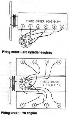
To avoid confusion, replace spark plug wires one at a time.
