Maverick and Comet Repair
Suspension
Front Shock Absorber
REMOVAL AND INSTALLATION
- Raise the hood. Remove the 3 nuts retaining the shock absorber upper mounting bracket to the spring tower.
- Jack up the front of the vehicle and install jack stands beneath the lower control arms.
- Remove the two shock absorber lower retaining nuts, washers, and insulators.
- Lift the shock absorber and upper mounting bracket assembly from the spring tower. Remove the two bolts retaining the upper bracket to the shock absorber and remove the bracket. Remove the insulators from the lower attaching studs.
- Check the shock absorber by wiping it clean and extending and compressing it several times. Severe leakage or weak damping action requires replacement. All standard equipment shock absorbers are non-refillable and they cannot be repaired. As a general rule, shock absorbers should be replaced in pairs (front and rear sets).
- To install, place the upper mounting bracket on the shock absorber and tighten the bolts to 10-16 ft. lbs. Install the insulators on the lower attaching studs.
- Position the shock absorber and upper mounting bracket assembly in the spring tower, making sure that the lower studs are located in the pivot plate holes.
- Install the two nuts on the shock absorber lower studs and tighten them to 8-12 ft. lbs.
- Install the 3 nuts retaining the shock absorber upper mounting bracket to the spring tower and torque them to 32-48 ft. lbs.
- Remove the jack stands and lower the vehicle.
Upper Ball Joint
INSPECTION
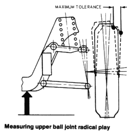
- Raise the vehicle on a hoist or floor jack so that the front wheels hang in the full down position. Install jack stands under the cross- member inboard of the lower control arms.
- Have an assistant grasp the wheel top and bottom and apply alternate in and out pressure to the top and bottom of the wheel.
- Radial play of 1/4 in. is acceptable measured at the inside of the wheel adjacent to the upper arm.
NOTE: This radial play measurement is multiplied at the
outer circumference of the tire and should not be measured here.
Measure only at the inside of the wheel.
NOTE: On 1972
and later models, Ford recommends that the entire upper control arm
be replaced if the ball joint is defective.

REMOVAL AND INSTALLATION
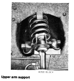
- Position a support between the upper arm and frame rail.
- Raise the vehicle and remove the tire and wheel.
- Remove the upper ball joint cotter pin and loosen the nut.
- Using a suitable tool, loosen the ball joint in the spindle.
- Remove the 3 ball joint retaining rivets using a large chisel.
- Remove the nut from the ball joint stud and remove the ball joint.
- Clean and remove all burrs from the ball joint mounting area of the control arm before installing the new ball joint.
- Install the ball joint in the upper arm using the service part nuts and bolts (if available). Do not attempt to rivet a new ball joint to the arm.
- Install and torque the ball joint stud nut to 60 ft. lbs. Then tighten the stud nut to the nearest cotter pin slot and install the cotter pin.
- Lubricate the new joint with a hand grease gun only, using an air pressure gun may loosen the ball joint seal.
- Install the wheel, lower the vehicle, and remove the upper arm support.
- Check the front end alignment.

Lower Ball Joint
INSPECTION
The lower
ball joint is an integral part of the lower control arm. If the
lower ball joint is defective the entire lower control arm must be
replaced.
- Raise the vehicle on a hoist or floor jack so that the front wheel falls to the full down position. Install jack stands under the crossmember inboard of the lower control arms.
- Have an assistant grasp the bottom of the tire and move the wheel in and out.
- As the wheel is being moved, observe the lower control arm where the spindle attaches to it.
- Any movement between
the lower part of the spindle and the lower control arm indicates a
bad control arm which must be replaced.
NOTE: During this check, the upper ball joint will be unloaded and may move; this is normal and not an indication of a bad ball joint. Also, do not mistake a loose wheel bearing for a worn ball joint.
Lower Control Arm
REMOVAL AND INSTALLATION
- Position an upper control arm support between the upper arm and the side rail.
- Raise the vehicle, position jackstands, and remove the wheel and tire.
- Remove the stabilizer bar-to-link attaching nut and disconnect the bar from the link.
- Remove the link bolt from the lower arm.
- Remove the strut bar-to-lower arm attaching nuts and bolts.
- Remove the lower ball joint cotter pin and back off the nut. Using a suitable tool, loosen the ball joint stud in the spindle.
- Remove the nut from the arm and lower the arm.
- Remove the lower arm-to-underbody cam attaching parts and remove the arm.
- To install, position the lower arm in the underbody and install the ball joint and cam attaching parts loosely.
- Install the stabilizer and strut and torque the attaching parts to 6-12 ft. lbs. and 80-115 ft. lbs. respectively.
- Torque the lower arm pivot to 75—100 ft. lbs. and the ball joint stud to 60-90 ft. lbs.
- Lower the car and remove the upper arm support.
- Front end alignment must be rechecked.
Upper Control Arm
When upper control arm
bushings become low on lubrication, they become very noisy. This can
often be corrected by lubrication and it is not necessary to replace
the bushings. On early models that do not contain grease plugs it is
necessary to drill and tap the bushing to accept a grease fitting.
On later models with grease plugs it is difficult to remove the plug
and grease the bushing with conventional tools. Ford has available
an upper A-arm lubrication kit which greatly eases the performance
of this operation.
NOTE: Because suspension damage to one
control arm generally affects the other, it is recommended that
upper and lower control arms, and their respective ball joints, be
replaced as a unit.
REMOVAL AND INSTALLATION
- Remove the shock absorber and upper mounting bracket from the car as an assembly.
- Raise the vehicle and remove the wheel and tire as an assembly.
- Install the spring compressor tool.
- Place a safety stand under the lower arm.
- Remove the cotter pin from the upper ball joint stud and loosen the nut.
- Using a suitable tool, loosen the ball joint in the spindle then, remove the nut and lift the stud from the spindle.
- Remove the upper arm attaching nuts from the engine compartment and remove the upper arm.
- To install the arm, position it on the mounting bracket and
install the attaching nuts on the inner shaft attaching bolts.
NOTE: The original equipment keystone-type lockwashers must be used with the inner shaft attaching nuts and bolts. - Install the upper ball joint stud in the spindle and tighten the nut to 60-90 ft. lbs. Install a new cotter pin.
- Remove the spring compressor and position spring on upper arm. Install wheel and check front end alignment.