Maverick and Comet Repair
Steering Column
Removal
1. Disconnect the negative battery
cable.
2. Disconnect the transmission rods at the steering
column.
3. Remove the two flex coupling-to-steering shaft nuts.
4. Remove the four screw bolts retaining the toe plate to the
dash panel (inside the vehicle).
5. Disconnect all electrical
connectors at the bottom of the column.
6. Remove the upper
column trim shroud at the instrument panel.
7. Remove the three
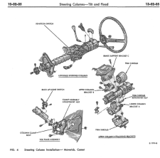
nuts securing the lower column bracket A to the brake support
bracket C and upper column bracket B (Fig. 4).
8. Drop the
column and remove it from the vehicle.
Installation
- Loosen the upper column bracket B so it slides freely in the slots.
- Loosen the toe plate cover column clamp bolt and slide the toe plate toward the steering wheel.
- Insert the steering column assembly through the dash panel opening to engage the steering shaft flange to the flex coupling.
- Raise the upper column bracket assembly over the two studs on the brake support bracket C and the one stud on the upper column bracket B (Fig. 4). Install the nuts finger tight.
- Insert a 1/4-inch diameter rod between the flex coupling fabric and the shaft flange. Tighten the flex coupling nuts to 10-22 lb-ft.
- Center the upper column in the instrument panel and torque the brake support bracket nuts 13-27 lb-ft
- Position the upper column bracket B flush with the extension lip on the brake support bracket C and secure the one retaining nut to the lower column bracket. Then, secure the upper column bracket B to the brake support bracket C with the two screw bolts. Torque to 13-17 lb-ft.
- Push the steering column toe plate cover tightly against the dash panel and secure with the four washer screws. Torque to 5-15 lb-ft.
- Check the column tube-to-steering shaft alignment. If not centered, loosen the two washer nuts at the clamp assembly and adjust if necessary. Secure the nuts to 10-22 lb-ft.
- Torque the column clamp bolt to 5-15 lb-ft.
- Replace the trim shrouds and connect all electrical connectors.
- Remove the 1/4-inch diameter rod at the flex coupling, adjust the transmission control lever rods and connect the negative battery cable.
- Check the column for proper operation
