Maverick and Comet Repair
Steering
Description
STEERING GEAR
The steering gear (Fig. 1) is of the worm and recirculating ball
type. The sector shaft is straddle mounted located in the cover
above the gear and a roller bearing in the housing below the gear.
The worm bearing preload is controlled by the large adjusting nut which is threaded into the housing. The sector shaft mesh load is controlled by an adjusting screw located in the housing cover.
The steering linkage consists of the Pitman arm, steering-arm-to-idler arm rod, idler arm and the spindle connecting rods (tie rods).
A steering gear identification tag is provided under one of the cover attaching bolts (Fig. 2).
ADJUSTMENTS
STEERING WORM AND
SECTOR
Gear Adjustments
The ball nut assembly and the
sector gear must be adjusted properly to maintain minimum steering
shaft end play (a factor of preload adjustment) and minimum backlash
between sector gear and ball nut. There are only two possible
adjustments within the recirculating ball-type steering gear, and
these should be made in the following order to avoid damage or gear
failure.
- Disconnect the Pitman arm from the steering Pitman-to-idler arm rod.
- Loosen the nut which locks the sector adjusting screw and turn the adjusting screw counterclockwise.
- Measure the worm bearing preload by attaching an in-lb torque wrench
to the steering wheel nut (Fig.4). With the steering wheel off
center,
read the pull required to rotate the input shaft approximately 1 1/2 turns either side of center. If the torque or preload is not within specification, adjust as explained in the next step. - Loosen the steering shaft bearing adjuster lock nut, and tighten or back off the bearing adjuster (Fig.1) to bring the preload within the specified limits.
- Tighten the steering shaft bearing adjuster lock nut, and recheck the preload.
- Turn the steering wheel slowly to either stop. Turn gently against toe stop to avoid possible damage to the ball return guides. Then rotate the wheel to center the ball nut Depending on the vehicle, check the specified number of turns in the specification chart at the end of this Part. Divide by two to determine the center position.
- Turn the sector adjusting screw clockwise until the specified torque is necessary to rotate the worm past its center (high spot) (Fig. 1).
- While holding the sector adjusting screw, tighten the sector adjusting screw locknut to specification, and recheck the backlash adjustment.
- Connect the Pitman arm to the steering arm-to-idler arm rod.
REMOVAL AND INSTALLATION
STEERING
GEAR
Removal
- Remove the bolt(s) that retains the flex coupling to the steering shaft.
- Remove the nut and lock washer that secures the Pitman arm to the sector shaft. Using Tool T64P-3590-F (Fig. 5), remove the Pitman arm from the sector shaft. Do not hammer on the end of the puller as this can damage the steering gear.
- To obtain clearance on some models equipped with standard transmission, it may be necessary to disconnect the clutch linkage. On some 8-cylinder models, it may be necessary to lower the exhaust system.
- Remove the steering gear.
Installation
- Position the steering gear and flex coupling in place then install and torque the steering gear-to-side rail bolts to specification (50-65 ft-lb).
- If the clutch linkage has been disconnected, reposition, install and adjust it. If the exhaust system has been lowered, reinstall it to its proper position.
- Position the Pitman arm and the sector shaft and install the attaching nut and lock washer. Torque the nut to 150-225 ft-lb.
- Install and connect the Hex coupling attaching nut(s) and torque it to specification.
STEERING GEAR
Disassembly
- Route the steering shaft to the center position.
- After removing the sector adjusting screw locknut and the housing cover bolts (Fig. 6), remove the sector shaft with the cover. Remove the cover from the shaft by turning the screw clockwise. Keep the shim with the screw.
- Loosen the worm bearing adjuster nut, and remove the adjuster assembly and the steering shaft upper bearing (Fig. 7).
- Carefully pull the steering shaft and ball nut from the housing, and remove the steeling shaft lower bearing. To avoid possible damage to the ball return guides, keep the ban nut from running down to either end of the worm. Disassemble the ball nut only if there is indication of binding or tightness.
- Remove the ball return guide clamp and the ball return guides from the ball nut. Keep the ball nut clamp side up until ready to remove the balls.
- Turn the ball nut over, and rotate the worm shaft from side to side until all the balls have dropped out of the nut into a dean pan. With the balls removed, the ball nut will slide off the worm.
- Remove the upper bearing cup from the bearing adjuster and the lower cup from the housing. It may be necessary to tap the housing or the adjuster on a block of wood to jar the bearing cups loose.
- If the preliminary inspection shows damage, press the sector shaft bearing and the oil seal from the housing (Fig. 8)
Assembly
- If the sector shaft bearing and oil seal have been removed, press a new bearing into the housing and install a new oil seal. Do not clean, wash or soak seals in cleaning solvent (Fig. 7). Apply the recommended steering gear lubricant to the bearing and seals.
- Install a bearing cup in the lower end of the housing and in the adjuster.
- If the seal in the bearing adjuster was removed, install a new seal.
- Insert the ball guides into the holes of the ball nut, tapping them lightly with a wood handle of a screw driver if necessary to seat them.
- Insert one half of the balls into the hole in the top of each ball guide. It may be necessary to rotate the shaft slightly one way, then in the opposite direction to distribute the balls in the circuit.
- After the balls are installed, install the ball guide clamp. Torque the screws to specification. Check the worm shaft to make sure that it rotates freely.
- Coat the threads of the steering shaft bearing adjuster, the housing cover bolts, and the sector adjusting screw with a suitable oil-resistant sealing compound. Do not apply sealer to female threads and especially avoid getting any sealer on the steering shaft bearings.
- Coat the worm bearings, sector shaft bearings, and gear teeth with steering gear lubricant.
- Clamp the housing in a vise, with the sector shaft axis horizontal, and position the steering shaft lower bearing in its cup.
- Position the steering shaft and ball nut assemblies in the housing.
- Position the steering shaft upper bearing on the top of the worm, and install the steering shaft bearing adjuster and the adjuster nut and bearing cup. Leave the nut loose.
- Adjust the worm bearing preload, using an in-lb torque wrench (Fig. 9). See the Specifications section for the specified preload.
- Position
the sector adjusting screw and adjuster shim, and check the end
clearance which should not exceed 0.002 inch between the screw
head and the end of the sector shaft. If clearance is greater than 0.002 inch, add enough shims to reduce the end play to within the 0.002 inch
tolerance. - Stan the sector shaft adjusting screw into the housing cover.
- Install a new gasket on the housing cover.
- Rotate the steering shaft until the ball nut teeth are in position to mesh with the sector gear, tilting the housing so that the ball will tip toward the housing cover opening.
- Lubricate the sector shaft journal and install the sector shaft and cover.
- With the housing cover turned out of the way fill
the gear with the specified amount of gear lubricant. Push the
housing cover and sector shaft assemblies into place, and install
the two top housing cover bolts. Do not tighten the cover bolts
until It is certain that there is some lash between
ball nut and sector gear teeth. Hold or push the cover away from the ball nut, then torque the bolts to specification. - After loosely installing the sector shaft adjusting screw lock nut, adjust the sector shaft mesh load. See the Specifications section for the specified mesh load; then, tighten the adjusting screw lock nut.
Specifications
Manual Steering
Gear Service Specifications
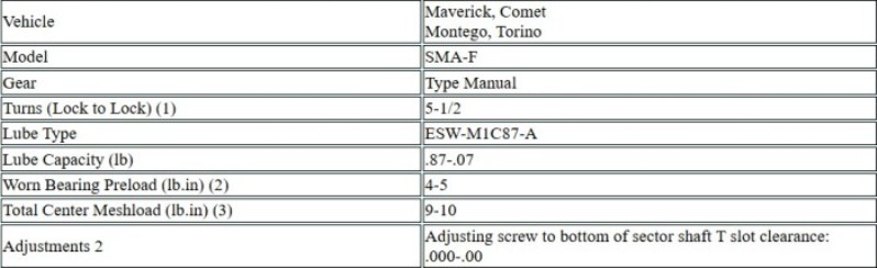
(1) Gear only - not attached
to Pitman arm.
(2) Torque required to rotate
input shaft at approximately 1-1/2 turns either side of
center (gear out of vehicle or Pitman arm disconnected.
(3) Required to rotate input shaft
and worn assembly past the center high point.
Manual Steering Gear Torque Limits (lb-ft)
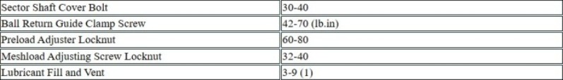
(1) Minimum of one thread must remain exposed when installed.
Special Service Tools
