Maverick and Comet Repair
Steering
Power Steering
POWER STEERING
SYSTEM ADJUSTMENTS
Control Valve Centering Spring Adjustment
- Raise the car and install safety stands.
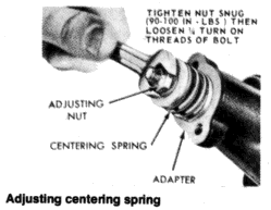
Remove the spring cap attaching screws and the spring cap.
CAUTION: Be very careful not to position the hoist adaptors of two-post hoists under the suspension and/or steering components. Place the hoist adaptors under the front suspension lower arms. - Tighten the adjusting nut snugly (about 90-100 in. lbs.); then
loosen the nut 1/4 turn (90°). Do not tighten the adjusting nut too
tightly. - Place the spring cap on the valve housing. Lubricate and install the attaching screws and washers. Tighten the screws to 72-100 in. lbs.
- Lower the car and start the engine. Check the steering effort using a spring scale attached to the steering wheel rim for a torque of more than 12 lbs.
Power steering control valve
Removal and installation
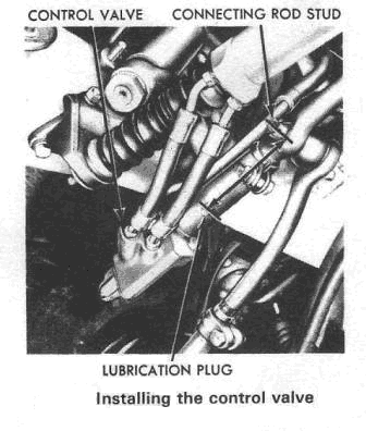
- Disconnect the four fluid line fittings at the control valve and drain the fluid into a suitable container. Turn the front wheels to the left and right several times to force all the fluid from the system.
- Loosen the clamping nut and bolt at the right end of the sleeve. Remove the roll pin from the steering arm-to-idler arm rod through the hole in the sleeve.
- Remove the control valve ball stud nut and using a suitable ball-joint separator disconnect the ball stud from the Pitman arm.
- Turn the front wheels fully to the left and remove the control valve by unscrewing it from the center link steering arm-to-idler arm rod.
- To install the valve, screw it onto the center link until about four threads are still visible on the link.
- Position the ball stud in the Pitman arm.
- Measure the distance between the center of the grease plug in the sleeve and the center of the stud at the inner end of the left spindle connecting rod. The distance should be 4-875 in (124 mm). If necessary, turn the valve on the center link to increase or decrease the distance.
- Align the hole in the steering arm-to-idler arm rod with the slot near the end of the valve sleeve. Install the roll pin in the rod hole to lock the valve on the rod.
- Tighten the valve sleeve clamp bolt and the ball stud nut. Install a new cotter pin.
- Fill the reservoir with steering gear fluid. Run the engine for a few minutes then turn the steering wheel from lock-to-lock several times and check the system for leaks.
- Check the fluid level and top-up if necessary.
- Check the effort to turn the steering wheel in both directions (see Centering Spring Adjustment above).
Power Steering Control Valve
Overhaul
- Clean all fluid and dirt from the exterior of the control valve.
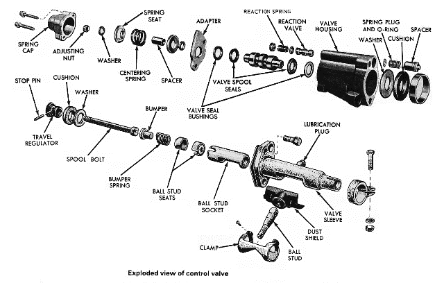
- Remove the two attaching screws and the centering spring cap from the valve housing.
- Mount the valve in a soft-jawed vise, hold it by the sleeve flange to prevent damage to the housing spool or sleeve.
- Undo the nut on the end of the valve spool bolt and remove the washers, spacer, centering spring, adaptor and bushing.
- Undo the two attaching bolts and separate the housing from the sleeve, then remove the plug from the sleeve.
- Push the valve spool out of the centering spring end of the valve housing and remove the seal from the spool.
- Remove the spacer, bushing and seal from the sleeve end of the housing.
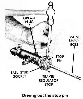
- Drive the stop pin out of the regulator stop with a punch.
- Turn the travel regulator stop counterclockwise in the sleeve and withdraw it from the sleeve.
- Remove the valve spool bolt, spacer and rubber washer.
- Remove the rubber boot and clamp from the valve sleeve.
- Slide the bumper, spring and ball stud seat out and remove the ball socket from the sleeve.
- Remove the return port hose seat and then the return port relief valve.
- Remove the plug, spring, 0-ring and reaction valve.
- Clean all the parts and inspect for wear, scoring or other damage. Install new seals and 0-rings. Before reassembling the control valve, coat all metal parts with steering gear fluid. Smear the seals with a silicone grease.
- Reassembly is the reverse of the dismantling procedure. Adjust the control valve centering spring as described above.
- Mount the valve in a vise and check the spool for freedom of movement by pushing forward on the cap end and then turning it round and pushing on the sleeve end.

Power Steering Cylinder
Removal
and Installation
- Disconnect the two fluid hoses from the power cylinder and allow them to drain into a container (photo).
- Remove the nuts, washer and insulator from the end of the power cylinder rod.
- Withdraw the cotter pin and remove the power cylinder stud-to-center link securing nut, then disconnect the cylinder from the center link, using a balljoint separator.
- Remove the insulator sleeve and washer from the end of the power cylinder rod.
- Installation is the reverse of the removal procedure. Fill the reservoir and bleed the air from the system.
Power steering cylinder seal - removal and installation
- Mount the power cylinder in a vise, taking care not to damage it, and remove the snap-ring from the end of the cylinder.
- Pull the piston rod out all the way to remove the scraper, bushing-and seals. If the seals do not come out with the piston rod use a sharp tool to pick them out taking care not to damage the shaft or seal seat,
- Use all the parts in the repair kit. Coat the seals and the piston rod with silicone grease and then install all the parts on the piston rod
- Push the rod all the way into the cylinder then tap the assembled parts fully in.
POWER STEERING PUMP
The
Ford-Thompson power steering pump is a belt-driven,
constant-displacement unit that uses a number of spring-loaded
slippers in the pump rotor to force oil from the inlet side to the
control valve. Openings in the metering pin allow a flow of
approximately 2 gal/min of fluid to the steering gear before the
flow control valve directs the excess fluid to the inlet side of the
pump again. Maximum pressure in the pump is limited by the pressure
relief valve which opens when the fluid pressure exceeds the maximum
pressure limits.
Removal And Installation
- Drain the fluid from the pump reservoir by disconnecting the fluid return hose at the pump. Then, disconnect the pressure hose from the pump.
- Remove the mounting bolts from the front of the pump. On eight-cylinder engines, there is a nut on the rear of the pump that is a nut on the rear of the pump that must be removed. After removal, move the pump inward to loosen the belt tension and remove the belt from the pulley. Then, remove the pump from the car.
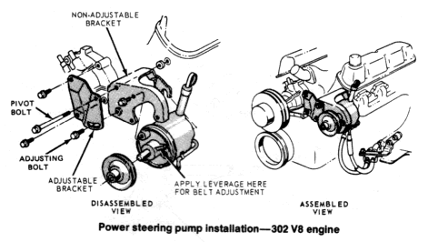
- To reinstall the pump, position it on the mounting bracket and loosely install the mounting bolts and nuts. Put the drive belt over the pulley and move the pump outward against the belt until the proper belt tension is obtained. Measure the belt tension with a belt tension gauge for the proper adjustment. Only in cases where a belt tension gauge is not available should the belt deflection method be used. If the belt deflection method is used, be sure to check with a belt tension gauge as soon as possible, since the deflection method is not accurate.
- Tighten the mounting bolts and nuts to the specified torque.
- Tighten the pressure hose fitting hex nut to the proper torque. Then, connect the pressure hose to the pump and tighten the hose nut to the proper torque.
- Connect the fluid return hose to the pump and tighten the clamp.
- Fill the pump reservoir with power steering fluid and bleed the air bubbles from the system.
- Check for leaks and recheck the fluid level. If necessary, add fluid to the proper level.
