Maverick and Comet Repair
Steering
Steering
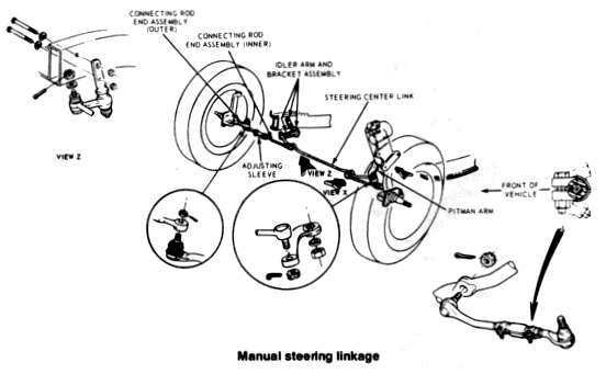
The manual and
power steering linkages consist of a pitman arm, arm-to-idler link,
idler arm and bracket assembly, and tie rod assemblies with
connecting sleeves. The steering gear is of the worm and
recirculating ball type, with worm bearing preload controlled by the
large adjusting nut threaded onto the housing itself. The sector
shaft mesh load is controlled by an adjusting screw in the housing
cover. The steering gear identification tag is located under one of
the cover securing bolts, and identifies the gear model, service
code and serial number or date manufactured.
The power steering system is a hydraulically controlled linkage-type system, and consists of an integral pump and fluid reservoir, control valve, power cylinder, fluid lines and steering linkage. The hydraulic pump, which is driven by belt from the crankshaft, draws fluid from the reservoir and provides pressure for the system. The pump contains a pressure relief valve which governs pressures produced in order to accommodate varying conditions. Fluid returns to the reservoir after passing from the pump to the control valve and power cylinder.
Steering Wheel
REMOVAL AND
INSTALLATION
NOTE; Make sure that the front wheels are
pointing straight ahead and the alignment marks on the steering
wheel and shaft are aligned prior to removal.
- Disconnect the negative battery cable.
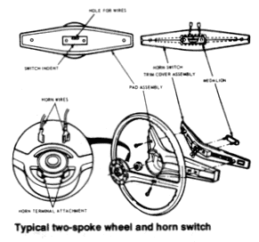
- Working from underside the steering wheel spoke, remove the crash pad retaining screws and lift the pad from the wheel. On models equipped with a center mounted horn button (hub), rotate the button (hub) counterclockwise Vi turn and lift it from the wheel.
- Disconnect the horn wires.
- Remove the
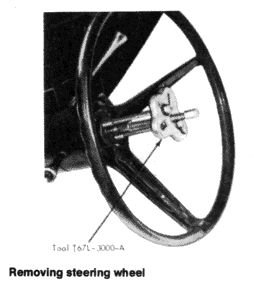
steering wheel nut. Using a steering wheel puller, such as the one
pictured in the illustration, remove the steering wheel from the
shaft.
CAUTION: Do not use a knock-off type steering wheel puller or strike the end of the steering shaft with a hammer. Either procedure may damage the steering shaft bearing or may collapse the steering column. - Transfer all serviceable parts to the new steering wheel (if applicable).
- Position the steering wheel on the steering shaft so that the marks on the wheel and shaft are properly aligned. Check again that the front wheels are pointing straight ahead, and that the steering wheel is in the normal position.
- Install a new steering wheel nut and torque to 30-40 ft. lbs. Connect the horn wires. Install the crash pad and screws, or the center hub (rotate clockwise).
- Connect the negative battery cable and test the horn and steering column for proper operation.
- Connect the pitman arm to the steering arm-to-idler arm rod.
Turn Signal And Hazard Flasher Switch
Assembly
REMOVAL AND INSTALLATION
- Follow Steps 1-4 under "Steering Wheel Removal and Installation."
- Unscrew the turn signal switch lever from the steering column.
- Remove the shroud from beneath the column.
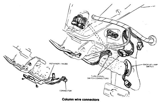
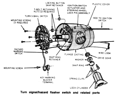
- Disconnect the steering column wiring connector plug from the bracket under the dash above the steering column. Remove the 3 screws retaining the turn signal/hazard flasher switch to the column.
- Carefully pull the wires and connector plug up through the hole in the flange casting and remove the switch.
- To install, route the wires and plug through the top of the column, so that they come out below the flange casting. Secure the switch to the column with the 3 retaining screws.
- Connect the plug to its mating plug at the lower end of the column.
- Install the shroud and turn signal lever on the steering column.
- Install the steering wheel as outlined under Steps 6, 7, and 8 of "Steering Wheel Removal and Installation."
- Test the operation of the turn signals and hazard flashers.
Manual Steering
STEERING GEAR
INSPECTION
Before any steering gear adjustments are
made, it is recommended that the front end of the car be raised and
a thorough inspection be made for stiffness or lost motion in the
steering gear, steering linkage, and front suspension. Worn or
damaged parts should be replaced, since a satisfactory adjustment of
the steering gear cannot be obtained if bent or badly worn parts
exist.
It is also very important that the steering gear be properly aligned in the car. Misalignment of the gear places a stress on the steering worm shaft, therefore a proper adjustment is impossible. To align the steering gear, loosen the mounting bolts to permit the gear to align itself. Check the steering gear mounting seat and if there is a gap at any of the mounting bolts, proper alignment may be obtained by placing shims where excessive gap appears. Tighten the steering gear bolts. Alignment of the gear in the car is very important and should be done carefully so that a satisfactory trouble-free gear adjustment may be obtained.
WORM AND SECTOR GEAR ADJUSTMENTS
The ball nut assembly and the sector gear must be adjusted properly
to maintain a minimum amount of steering shaft endplay and a minimum
amount of backlash between the sector gear and the ball nut. There
are only two adjustments that may be done on this steering gear and
they should be done as given below:
- Disconnect the pitman arm from the steering pitman-to-idler arm rod.
- Loosen the locknut on the sector shaft adjustment screw and turn the adjusting screw counterclockwise.
- Measure the worm bearing preload by attaching an in. lbs. torque wrench to the steering wheel nut. With the steering wheel off center, note the reading required to rotate the input shaft about 1/2 turns to either side of center. If the torque reading is not about 4-5 in. lbs., adjust the gear as given in the next step.
- Loosen the steering shaft bearing adjuster locknut and tighten or back off the bearing adjusting screw until the preload is within the specified limits.
- Tighten the steering shaft bearing adjuster locknut and recheck the preload torque.
- Turn the steering wheel slowly to either stop. Turn gently against the stop to avoid possible damage to the ball return guides. Then rotate the wheel 2-3/4 turns to center the ball nut.
- Turn the sector adjusting screw clockwise until the proper torque (9-10 in. lbs.) is obtained that is necessary to rotate the worm gear past its center (high spot).
- While holding the sector adjusting screw, tighten the sector screw adjusting locknut to 32-40 ft. lbs. and recheck the backlash adjustment.