Maverick and Comet Repair
Fuel System
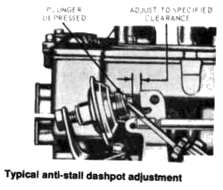
ANTI-STALL DASHPOT ADJUSTMENT
All
Carburetors
Having made sure that the engine idle speed
and mixture are correct and that the engine is at normal operating
temperature, loosen the anti-stall dashpot locking nut (see
accompanying illustration). With the throttle held closed, depress
the plunger with a screwdriver blade and measure the clearance
between the throttle lever and the plunger tip. If the clearance is
not as specified in the "Carburetor Adjustments" table, turn the
dashpot until the proper clearance is obtained between the throttle
lever and the plunger tip. After tightening the locking nut, recheck
the adjustment.
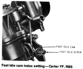
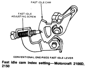
FAST IDLE CAM INDEX SETTING
Carter YF, YFA, and RBS
- Position the fast idle screw on the kick-down step of the fast idle cam against the shoulder of the high step.
- Adjust by bending the choke plate connecting rod to obtain the specified clearance between the lower edge of the choke plate and the carburetor bore.
imageAutolite (Motorcraft) 21 ODD, 2150
1971-72
- Loosen the choke thermostatic spring housing retaining screws and position the housing 90° in the rich direction.
- Position the fast idle speed screw at the kick-down step of the fast idle cam. This kick- down step is identified by a small "V" stamped in the side of the casting.
- Be sure that the fast idle cam is in the kick-down position while checking or adjusting the fast idle cam clearance. Check the clearance between the lower edge of the choke plate and the wall of the air horn by inserting a drill of the specified diameter between them. Adjustment may be accomplished by turning the fast idle cam adjusting screw clockwise to increase or counterclockwise to decrease the clearance.
- Set the choke thermostatic spring housing to specifications, and adjust the anti-stall dashpot, idle speed, and fuel mixture.
1973-77
- Loosen the choke thermostatic spring housing retaining screws and rotate the housing 90° in the rich direction.
- Position the fast idle speed screw or lever on the high step of the cam.
- Depress the choke pull-down diaphragm against the diaphragm stop screw thereby placing the choke in the pull-down position.
- While holding the choke pull-down diaphragm depressed, slightly open the throttle and allow the fast idle cam to fall.
- Close the throttle and check the position of the fast idle cam or lever. When the fast idle cam is adjusted correctly, the screw should contact the "V" mark on the cam. Adjustment is accomplished by rotating the fast idle cam adjusting screw as needed.
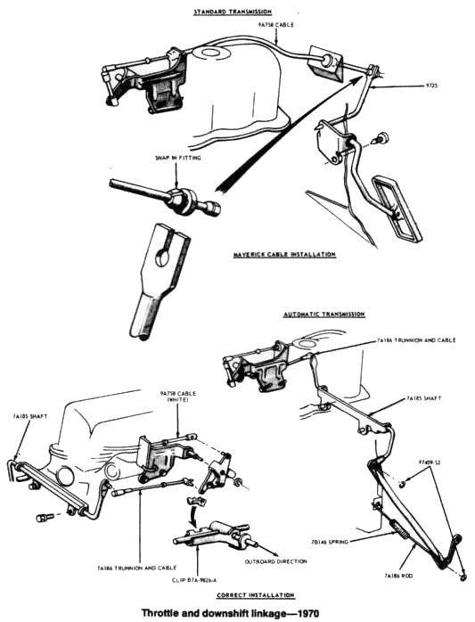
THROTTLE AND DOWNSHIFT LINKAGE ADJUSTMENT
Vehicles With Automatic
Transmission
1970
- Disconnect the throttle return spring.
- Remove the trunnion and cable at the bellcrank.
- Hold the transmission linkage in full downshift against the stop.
- Hold the carburetor throttle lever at wide-open throttle against its stop.
- Adjust the trunnion at the bellcrank until the ball stud on the shaft and the ball stud receiver on the cable align. Then turn the trunnion one full turn to increase the length.
- Release the transmission and throttle linkage to the normal free position, and install the return spring.
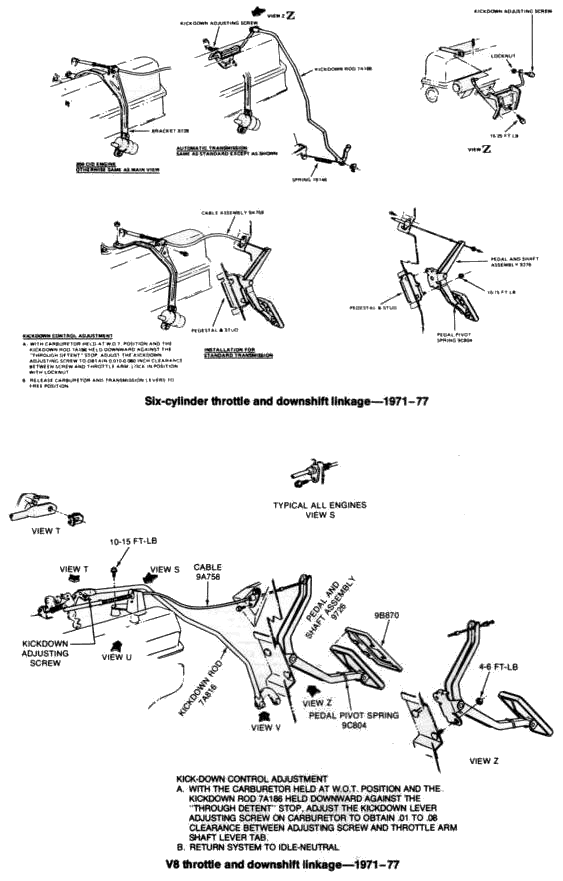
1972-77
- Disconnect the throttle return spring.
- With the throttle shaft lever held in the wide-open throttle (WOT) position, and the downshift (kick-down) rod held downward against the through detent stop, adjust the downshift (kickdown adjusting) screw to provide a 0.050-0.070 in. clearance on 1971-72 models, and a 0.010-0.080 in. clearance on 1973-76 models, between the screw and the throttle shaft lever (arm).
- Release the carburetor and transmission levers to the free position, and install the return spring.
Motorcraft Variable
Venturi
2700W
For 1977, Ford's new 2700W (Variable Venturi)
carburetor is available on California cars equipped with the 302
V8. Since the design of this carburetor differs considerably
from the other carburetors in the Ford lineup, a little theory
might be helpful here.
In exterior appearance, the variable
venturi carburetor is similar to conventional carburetors, and
like a conventional carburetor, it uses a normal float and fuel
bowl system. However, the similarity ends there. In place of a
normal choke plate and fixed area venturis, the 2700W carburetor
has a pair of small oblong castings in the top of the upper
carburetor body where you would normally expect to see the choke
plate. These castings slide back and forth across the top of the
carburetor in response to fuel/air demands. Their movement is
controlled by a spring loaded diaphragm valve regulated by a
vacuum signal taken below the Venturis in the throttle bores. As
the throttle is opened, the strength of the vacuum signal
increases, opening the Venturis and allowing more air to enter
the carburetor. Fuel is admitted into the venturi area by means
of tapered metering rods that fit into the main jets. These rods
are attached to the Venturis, and, as the venturis open or close
in response to air demand, the fuel needed to maintain the
proper mixture increases or decreases as the metering rods slide
in the jets. In comparison to a conventional carburetor with
fixed Venturis and a variable air supply, this system provides
much more precise control of the fuel/air supply during all
modes of operation. Because of the variable venturi principle,
there are fewer fuel metering systems and fuel passages. The
only auxiliary fuel metering systems required are an idle trim,
accelerator pump (similar to a conventional carburetor),
starting enrichment, and cold running enrichment.
NOTE:
Adjustment, assembly and disassembly of this carburetor require
a number of special tools which are available only from your
Ford dealer. Do not attempt to adjust or rebuild the carburetor
without first purchasing the special tools.
