Maverick and Comet Repair
Fuel System
Carburetors
Carburetor applications are as
follows:
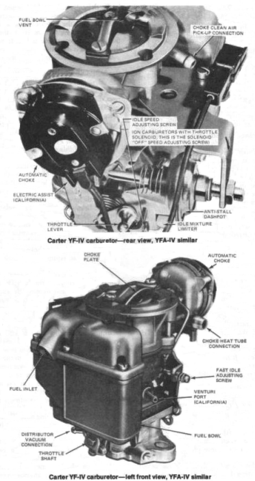
• 1970-74 170, 200 Six—Carter YF 1 bbl
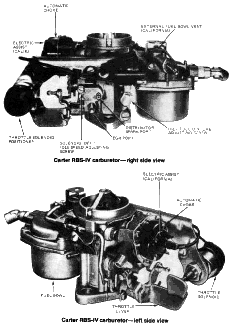
• 1970-74 250
Six—Carter RBS 1 bbl
• 1975-76 200, 250 Six—Carter YFA 1 bbl
•
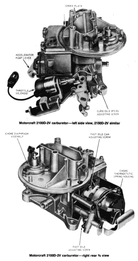
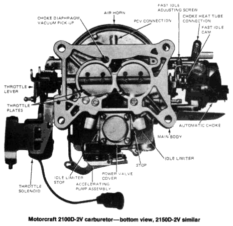
1971-74 302 V8—Autolite (Motorcraft) 2100D 2 bbl
• 1975-77 302
V8—Motorcraft 2150 2 bbl
• 1977 302 V8 (California)—Motorcraft
2700 W (Variable Venturi)
In accordance with Federal emissions
regulations, all 3 carburetors are equipped with idle mixture screw
limiter caps. These caps are installed to prevent tampering with the
carburetor fuel mixture screw(s) so that the engine cannot be
adjusted to a richer idle mixture. Most models are equipped with a
throttle positioner solenoid. The purpose of a throttle solenoid is
to prevent the engine from running on (dieseling) after the ignition
is turned off. dieseling is a common occurrence with many cars using
emission control systems that require a leaner fuel mixture, a
higher operating temperature, and a higher curb idle speed. The
throttle solenoid prevents running-on and dieseling by closing the
throttle plate(s) after the key is turned off, thereby shutting off
the air and gas to the overheated combustion chambers.
THROTTLE SOLENOID (ANTI-DIESELING SOLENOID) TEST
- Turn the ignition key on and open the throttle. The solenoid plunger should extend (solenoid energize).
- Turn the ignition off. The plunger should retract, allowing the
throttle to close.
NOTE: With the anti-dieseling solenoid de-energized, the carburetor idle speed adjusting screw must make contact with the throttle shaft to prevent the throttle plates from jamming in the throttle bore when the engine is turned off. - If the solenoid is functioning properly and the engine is still
dieseling, check for one of the following:
a.) High idle or engine shut off speed;
b.) Engine timing not set to specification;
c.) Binding throttle linkage;
d.) Too low an octane fuel being used.
Correct any of these problems as necessary. - If the solenoid fails to function as outlined in steps 1-2, disconnect the solenoid leads; the solenoid should de-energize. If it does not, it is jammed and must be replaced.
- Connect the solenoid to a 12 V power source and to ground. Open the throttle so that the plunger can extend. If it does not, the solenoid is defective.
- If the
solenoid is functioning correctly and no other source of trouble can
be found, the fault probably lies in the wiring between the solenoid
and the ignition switch or in the ignition switch itself. Remember
to reconnect the solenoid when finished testing.
NOTE: On some 1970-71 models, dieseling may occur when the engine is turned off because of feedback through the alternator warning light circuit. A diode kit is available from Ford to cure this problem. A failure of this diode may also lead to a similar problem.
REMOVAL AND INSTALLATION
- Remove the air cleaner.
- Disconnect the throttle cable or rod at the throttle lever. Disconnect the distributor vacuum line, exhaust gas recirculation line (1973 and later models), inline fuel filter, choke heat tube and the positive crankcase ventilation hose at the carburetor.
- Disconnect the throttle solenoid (if so equipped) and electric choke assist (1973 and later models so equipped), at their connectors.
- Remove the carburetor retaining nuts. Lift off the carburetor carefully, taking care not to spill any fuel. Remove the carburetor mounting gasket and discard it. Remove the carburetor mounting spacer, if so equipped, from the intake manifold.
- Prior to installation, clean the gasket mounting surfaces of the intake manifold, spacer (if so equipped), and carburetor. When using a spacer, use two new gaskets, sandwiching the spacer between the gaskets. If a spacer is not used, only one new carburetor mounting gasket is required.
- Place the new gasket(s) and spacer (if so equipped) on the carburetor mounting studs. Position the carburetor mounting studs. Position the carburetor on top of the gasket and hand tighten the retaining nuts. Then tighten the nuts in a criss-cross pattern to 10-15 ft. lbs.
- Connect the throttle linkage, the distributor vacuum line, exhaust gas recirculation line, exhaust gas recirculation line (1973 and later models), inline fuel filter, choke heat tube, positive crankcase ventilation hose, throttle solenoid (if so equipped) and electric-choke assist (models so equipped).
- Adjust the curb idle speed, the idle fuel mixture and the accelerator pump stroke (2100D and 2150 only). Install the air cleaner.