Maverick and Comet Repair
Engine Repair
PRELIMINARY VALVE ADJUSTMENT
All Maverick and Comet engines are equipped with hydraulic valve
lifters. Valve systems with hydraulic valve lifters operate with
zero clearance in the valve train and. because of this, the rocker
arms are non-adjustable. The only means by which valve system
clearances can be altered is by installing 0.060 in. over or
undersize pushrods. Because of the hydraulic lifter's natural
ability to compensate for slack in the valve train, all components
of the valve system should be checked for wear if there is excessive
play in the system.
When a valve in the engine is in the closed position, the valve lifter is resting on the base circle of the camshaft lobe and the pushrod is in its lowest position. To remove this additional clearance from the valve train, the valve lifter expands to maintain zero clearance in the valve system. When a rocker arm is loosened or removed from the engine, the lifter expands to its fullest travel. When the rocker arm is reinstalled on the engine, the proper valve setting is obtained by tightening the rocker arm to a specified limit. With the lifter fully expanded, if the camshaft lobe is on a high point, it will require excessive torque to compress the lifter and obtain the proper setting. Because of this, when any component of the valve system has been removed, a preliminary valve adjustment procedure must be followed to ensure that when the rocker arm is reinstalled on the engine and tightened, the camshaft lobe for that cylinder is in the low position.
6 Cylinder
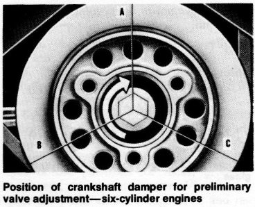
- Crank the
engine until the TDC mark on the crankshaft damper is aligned with
timing pointer on the cylinder front cover.
Position of crankshaft damper for preliminary valve adjustment—six-cylinder engines - Scribe a mark on the damper at this point.
- Scribe two more marks on the damper, each equally spaced from the first mark (see illustration).
- With the engine on TDC of the compression stroke (mark A aligned with the pointer), back off the rocker arm adjusting nut until there is end-play in the pushrod. Tighten the adjusting nut until all clearance is removed, then tighten the adjusting nut one additional turn. To determine when all clearance is removed from the rocker arm, turn the pushrod with the fingers. When the pushrod can no longer be turned, all clearance has been removed.
- Repeat this procedure for each valve, turning the crankshaft 1/3 turn to the next mark each time and following the engine firing order of 1-5-3-6-2-4.
302 V8
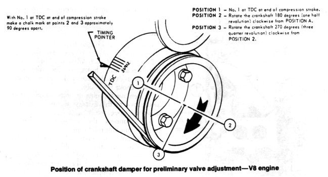
- Crank the engine until no. 1 cylinder is at TDC of the compression stroke and the timing pointer is aligned with the mark on the crankshaft damper.
- Scribe a mark on the damper at this point.
- Scribe two additional marks on the damper (see illustration).
- With the timing pointer aligned with mark "A" on the damper, tighten
the following valves to the specified torque:
No. 1, 7, and 8 Intake; No. 1, 5, and 4 Exhaust. - Rotate the crankshaft 180° to
point "B" and tighten the following valves:
No. 5 and 4 Intake; No. 2 and 6 Exhaust. - Rotate the crankshaft 270° to point "C"
and tighten the following valves:
No. 2, 3, and 6 Intake; No. 7, 3, and 8 Exhaust.