Maverick and Comet Repair
Emission Controls
SPARK DELAY VALVE
- Locate the spark delay valve in the distributor vacuum line and disconnect it from the line.
- Install a new spark delay valve in the line, making sure that the black end of the valve is connected to the line from the carburetor and the color coded end is connected to the line from the spark delay valve to the distributor.
DIST-O-VAC AND ESC TEMPERATURE SENSOR
- Open the right door and remove the two screws that attach the temperature sensor to the right door pillar.
- Disconnect the lead wires from the temperature sensor.
- Connect the lead wires to the new sensor.
- Position the sensor on the door pillar and install the attaching screws
DIST-O-VAC AND ESC SPEED SENSOR
- Disconnect the lead wires from the sensor.
- Disconnect the speed sensor from the speedometer cable.
- Position the O-rings on both ends of the new speed sensor.
- Connect both ends of the speedometer cable to the speed sensor.
- Connect the lead wires to the speed sensor.
ESC AMPLIFIER
- Locate the amplifier under the instrument panel, near the glove compartment.
- Disconnect the wiring harness from the amplifier.
- Remove the two amplifier attaching screws and remove the amplifier.
- Position a new amplifier under the instrument panel and connect the wiring harness to it.
- Install the two amplifier attaching screws.
ESC DISTRIBUTOR VACUUM MODULATOR VALVE
- Tag the hoses that attach to the modulator and disconnect them from the amplifier.
- Disconnect the lead wires from the modulator.
- Remove the #2 left front valve cover bolt (six-cylinder) or the inboard left front valve cover bolt and remove the modulator.
- Position the new modulator on the valve cover and install the attaching bolt.
- Connect the wires and hoses to the modulator.
THERMACTOR AIR PUMP
- Disconnect the air outlet hose at the air pump.
- Loosen the pump belt tension adjuster.
- Disengage the drive belt.
- Remove the mounting bolt and air pump.
- To install, position the air pump on the mounting bracket and install the mounting bolt.
- Place drive belt in pulleys and attach the adjusting arm to the air pump.
- Adjust the drive belt tension to specifications and tighten the adjusting arm and mounting bolts.
- Connect the air outlet hose to the air pump.
THERMACTOR AIR PUMP FILTER FAN
- Loosen the air pump adjusting arm bolt and mounting bracket bolt to relieve drive belt tension.
- Remove drive pulley attaching bolts and pull drive pulley off the air pump shaft.
- Pry the
outer disc loose; then, pull off the centrifugal filter fan with
slip-joint pliers.
CAUTION: Do not attempt to remove the metal drive hub. - Install a new filter fan by drawing it into position, using the pulley and bolts as an installer. Draw the fan evenly by alternately tightening the bolts, making certain that the outer edge of the fan slips into the housing.
NOTE: A slight interference with the housing bore is normal. After a new fan is installed, it may squeal upon initial operation, until its outer diameter sealing lip has worn in, which may require 20 to 30 miles of operation.
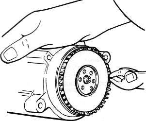
Thermactor air pump filter fan removal
THERMACTOR CHECK VALVE
- Disconnect the air supply hose at the valve. (Use a 1-1/4 in. crowfoot wrench, the valve has a standard, right-hand pipe thread.)
- Clean the threads on the air manifold adaptor (air supply tube on
302 V8 engine) with a wire brush. Do not blow compressed
air through the check valve in either direction. - Install the check valve and tighten.
- Connect the air supply hose.
THERMACTOR AIR BY-PASS VALVE
- Disconnect the air and vacuum hoses at the air by-pass valve body.
- Position the air by-pass valve, and connect the respective hoses.