Maverick and Comet Repair
Emission Controls
Exhaust Gas Recirculation System
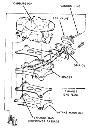
All 1973 and later models are equipped with an Exhaust Gas
Recirculation (EGR) system to control oxides of nitrogen.
On V8
engines, exhaust gases travel through the exhaust gas crossover
passage in the intake manifold. A portion of these gases are
diverted into a spacer which is mounted under the carburetor. The
EGR control valve, which is attached to the rear of the spacer,
consists of a vacuum diaphragm with an attached plunger which
normally block off exhaust gases from entering the intake manifold.
On 6 cylinder engine, an external tube carries exhaust manifold
gases to the carburetor spacer. On all models, the EGR Valve is
controlled by a vacuum line from the carburetor which passes through
a ported vacuum switch. The EGR ported vacuum switch provides vacuum
to the EGR valve at coolant temperature above 125°F. The vacuum
diaphragm then opens the EGR valve permitting exhaust gases to flow
through the carburetor spacer and enter the intake manifold where
they combine with the fuel mixture and enter the combustion
chambers. The exhaust gases are relatively oxygen-free, and tend to
dilute the combustion charge. This lowers peak combustion
temperature thereby reducing oxides of nitrogen.
EGR SYSTEM VENTURI
VACUUM AMPLIFIER
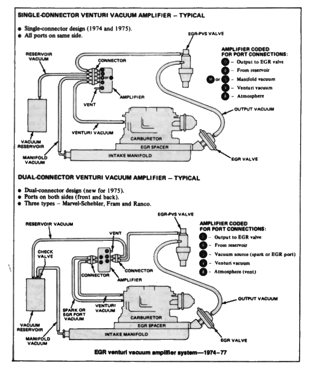
On all 1974 California* models, and
most 1975-77 50 states models, the EGR system has been modified to
include a venturi vacuum amplifier. The amplifier is used to boost a
relatively weak venturi vacuum signal in the throat of the
carburetor into a strong intake manifold vacuum signal to operate
the EGR valve. This device improves drivability by more closely
matching venturi air flow and EGR flow.
The amplifier features a vacuum reservoir and check valve to maintain an adequate vacuum supply regardless of variations in engine manifold vacuum. Also used in conjunction with the amplifier, is a relief valve, which will cancel the output EGR vacuum signal whenever the venturi vacuum signal is equal to, or greater than, the intake manifold vacuum. Thus, the EGR valve may close at or near wide-open throttle acceleration, when maximum power is needed.
EGR/Coolant Spark
Control (CSC) System
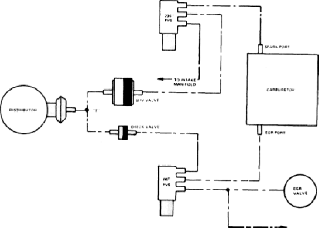
The EGR/CSC system is used on most
1974 and later models. It regulates both distributor spark advance
and the EGR valve operation according to coolant temperature by
sequentially switching vacuum signals.
The major EGR/CSC system
components are:
- 95°F EGR-PVS valve;
- Spark Delay Valve (SDV);
- Vacuum check valve.
When the engine coolant temperature is below 82°F, the EGR-PVS valve admits carburetor EGR port vacuum (occurring at about 2,500 rpm) directly to the distributor advance diaphragm, through the one-way check valve.
At the same time, the EGR-PVS valve shuts ofF
carburetor EGR vacuum to the EGR valve and transmission diaphragm.
When engine coolant temperature is 95°F and above, the EGR-PVS valve
is actuated and directs carburetor EGR vacuum to the EGR valve and
transmission instead of the distributor. At temperatures between
82-95°F, the EGR-PVS valve may be open, closed or in mid-position.
EGR/CSC system schematic
The SDV valve delays carburetor spark vacuum to the distributor advance diaphragm by restricting the vacuum signal through the SDV valve for a predetermined time. During normal acceleration, little or no vacuum is admitted to the distributor advance diaphragm until acceleration is completed, because of (1) the time delay of the SDV valve and (2) the re-routing of EGR port vacuum if the engine coolant temperature is 95°F or higher.
The check valve blocks off vacuum signal from the SDV to the EGR-PVS so that carburetor spark vacuum will not be dissipated when the EGR-PVS is actuated above 95°F.
Temperature Activated
Vacuum (TAV) System
1973 Mavericks and Comets using the
250 six-cylinder engine and automatic transmission built before
March 15, 1973 are equipped with a Temperature Activated Vacuum
(TAV) system to control distributor spark advance. The system
contains a 3-way solenoid valve, an ambient temperature switch
located in the front door hinge pillar, a vacuum bleed line to the
carburetor airhorn and a spark delay valve.
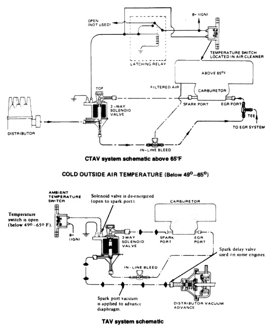
When the ambient temperature is above 60°F, the contacts in the temperature sensor close and complete the circuit to the 3-way solenoid. This energizes the solenoid and connects the EGR vacuum port on the carburetor to the distributor vacuum advance. The EGR vacuum signal is weaker than the normal spark port vacuum signal, thus supplying less vacuum advance once the outside temperature rises above 60°F. When the ambient temperature is below 49°F, the solenoid is de-energized and the distributor vacuum advance operates in the normal manner, thus aiding cold weather drivability.
Cold Temperature
Activated Vacuum (CTAV) System
1973 Mavericks and Comets
using the 250 six-cylinder engine and automatic transmission built
on or after March 15, 1973, as well as all 1974-77 models using the
250 six and automatic transmission are equipped with a Cold
Temperature Activated Vacuum (CTAV) system to control distributor
spark advance. This system is basically a refinement of the TAV
system with the temperature switch relocated in the air cleaner and
a latching relay added to maintain a strong vacuum signal at the
distributor, whether it be EGR port or spark port carburetor vacuum,
and to keep the system from intermittently switching vacuum signals
when the intake air is between 49 and 60°F. When the temperature
switch closes at 60°F, the latching relay (normally off) is
energized and stays on until the ignition switch is turned off. The
latching relay then overrides the temperature switch and forces the
solenoid valve to keep the spark port vacuum system closed and open
the EGR port vacuum system. This prevents full vacuum advance, once
the engine is warmed-up, thereby lowering emissions.
Thermactor System
1974 California models, as well as all 1975-77 50 states models are
equipped with a Thermactor emission control system. This system is
used in addition to the existing PCV, fuel evaporative, IMCO, EGR,
and catalytic converter control systems.
NOTE: For 1977, the Thermactor system has been deleted for all cars with automatic transmissions (49 states version only). The Thermactor emission control system makes use of a belt-driven air pump to inject fresh air into the hot exhaust stream through the engine exhaust ports. The result is the extended burning of those fumes which were not completely ignited in the combustion chamber, and the subsequent reduction of some of the hydrocarbon and carbon monoxide content of the exhaust emissions into harmless carbon dioxide and water.
The Thermactor system is composed of the following components:
- Air supply pump (belt-driven)
- Air by-pass valve
- Check valves
- Air manifolds (internal or external)
- Air supply tubes (on external manifolds only).
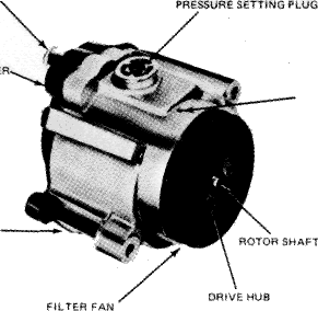
Air for the Thermactor system is cleaned by means of a centrifugal filter fan mounted on the air pump driveshaft. The air filter does not require a replaceable element.
To prevent excessive pressure, the air pump is equipped with a pressure relief valve which uses a replaceable plastic plug to control the pressure setting.
The Thermactor air pump has sealed bearings which are lubricated for the life of the unit, and pre-set rotor vane and bearing clearances, which do not require any periodic adjustments.
Air supply pump—1974 type shown; 1975-77 pump similar
The air supply from the pump is controlled by the air by-pass valve, sometimes called a dump valve. During deceleration, the air bypass valve opens, momentarily diverting the air supply through a silencer and into the atmosphere, thus preventing backfires within the exhaust system.
A check valve is incorporated in the air inlet side of the air manifolds. Its purpose is to prevent exhaust gases from backing up into the Thermactor system. This valve is especially important in the event of drive belt failure, and during deceleration, when the air by-pass valve is dumping the air supply.
The air manifolds and air supply tubes channel the air from the Thermactor pump into the exhaust ports of each cylinder, thus completing the cycle of the Thermactor system.
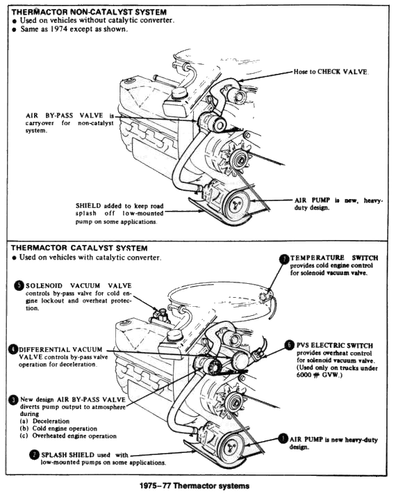
The Thermactor system used on 1975-77 cars with catalytic converters incorporates several components to prevent excessive converter temperatures from developing. Since the catalyst requires large quantities of oxygen to function, an air by-pass valve and a vacuum differential (VDV) valve are used to control temperatures by dumping air from the Thermactor pump to the atmosphere instead of delivering it to the catalyst.
The purpose of these valves is to "dump" air
during periods of vacuum failure, the rich exhaust gas condition
during deceleration, prevent backfire when the exhaust gases are
overly rich, and provide pressure relief (due to excessive air pump
volume or restriction downstream).
The air by-pass valve used
with catalytic converters differs from the valve used on cars
without converters, and can be identified by the vacuum port on top
of the valve. The valve functions as follows:
During normal operation, engine intake manifold vacuum applied through the VDV holds the valve upward, allowing thermactor air to flow to the cylinder head(s) and blocking the vent port. When engine intake manifold vacuum rises or drops sharply (such as during acceleration or deceleration, or system blockage or failure), the VDV operates and momentarily cuts off the vacuum to the by-pass valve. The spring pulls the stem down, seating the valve to cut off pump air to the exhaust manifold, and opening the dump valve at the lower end of the by-pass valve to momentarily divert the pump air to the atmosphere. In the case of excess pump volume or a downstream restriction, the excess pressure will unseat the valve in the lower portion of the by-pass valve and allow a partial flow of pump air to the atmosphere. At the same time, the valve in the upper part of the by-pass is still unseated, allowing a partial flow of pump air to the exhaust manifold to meet system requirements.
The vacuum differential valve (VDV) controls
the operation of the new by-pass valve used with catalytic converter
equipped systems.
The VDV is inserted in the vacuum control line
to the by-pass valve and serves to cut off the vacuum and
de-energize the by-pass valve. The differential valve consists of a
diaphragm connected to a dump valve that controls the vacuum to the
by-pass valve. During normal operation, vacuum is equalized on both
sides of the diaphragm and the spring holds the dump valve closed.
When sudden higher than normal vacuum is encountered, such as under
deceleration conditions, vacuum is higher on the dump valve side of
the diaphragm and the diaphragm operates the dump valve. As the dump
valve operates, the vacuum signal to the by-pass valve is diverted
through the built-in filter system to atmosphere. When the vacuum
bleeding through the by-pass timing orifice in the VDV has equalized
on both sides of the diaphragm, the diaphragm return spring once
again closes the dump valve and applies vacuum to the by-pass valve,
which again applies pump air to the exhaust ports.