Maverick and Comet Repair
Emission Controls
HEATED AIR INTAKE SYSTEM
The heated air intake portion of the air cleaner consists of a
thermostat (1970-72 models) or bimetal switch (1973-77 models), and
vacuum motor (1973-77 models), and a spring-loaded temperature
control door in the snorkel of the air cleaner. The temperature
control door is located between the end of the air cleaner snorkel
which draws in air from the engine compartment and the duct that
carries heated air up from the exhaust manifold. When under hood
temperature is below 90°F, the temperature control door blocks off
under hood air from entering the air cleaner and allows only heated
air from the exhaust manifold to be drawn into the air cleaner. When
under hood temperature rises above 130°F, the temperature control
door blocks off heated air from the exhaust manifold and allows only
under hood air to be drawn into the air cleaner.
By controlling the temperature of the engine intake air this way, exhaust emissions are lowered and fuel economy is improved. In addition, throttle plate icing is reduced, and cold weather drivability is improved from the necessary leaner mixtures.
Temperature-operated duct and valve assembly
Vacuum-operated duct and valve assembly
DUAL DIAPHRAGM DISTRIBUTORS
Dual diaphragm distributors are installed
in most 1970—77 models. The best way to check for a dual diaphragm
distributor is to count the number of vacuum hoses attached to the
distributor vacuum chamber. One hose means you have a single
diaphragm distributor, and two hoses denotes a dual diaphragm unit.
The dual distributor diaphragm is a two-chambered housing which is mounted on the side of the distributor. The outer side of the housing is a distributor vacuum advance mechanism, connected to the carburetor by a vacuum hose. The purpose of the vacuum advance is to advance ignition timing according to the conditions under which the engine is operating. This device has been used on automobiles for many years now and its chief advantage is economical engine operation. The second side of the dual diaphragm is the side that has been added to help control engine exhaust emissions at idle and during deceleration.
The inner side of the dual diaphragm is connected by a vacuum hose to the intake manifold. When the engine is idling or decelerating, intake manifold vacuum is high and carburetor vacuum is low. Under these conditions, intake manifold vacuum, applied to the inner side of the dual diaphragm, retards ignition timing to promote more complete combustion of the air fuel mixture in the engine combustion chambers.
PORTED VACUUM SWITCH
(DISTRIBUTOR VACUUM CONTROL VALVE)
Ported vacuum
switches have been used in most 1970-77 models to switch vacuum
signals with varying engine coolant temperatures. They may have two,
three, or four vacuum ports, and, on 1975-77 models equipped with a
catalytic converter and Thermactor air pump system, a set of
electrical contacts. On some late model configurations, there may be
as many as three or four separate ported vacuum switches, each with
their own special function. PVS switches may be used to switch
vacuum signals on an ignition spark control system to improve cold
start drivability or lower emissions, to cut off exhaust gas
recirculation until a predetermined engine coolant temperature is
reached, to vent Thermactor air pump air to the atmosphere under
certain engine conditions, to regulate a vacuum operated heat
control valve in the exhaust manifold, or (especially on air
conditioned cars), to provide extra ignition advance and subsequent
higher idle speed should the engine begin to overheat.
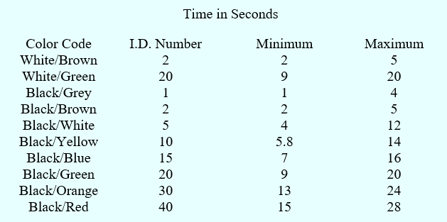
SPARK DELAY VALVE
The spark delay valve is a plastic, spring-loaded, color coded valve
which is installed in the vacuum line to the distributor advance
diaphragm on many 1972-77 models. Under heavy throttle application,
the valve will close, blocking normal carburetor vacuum to the
distributor. After the designated period of closed time, the valve
opens, restoring the carburetor vacuum to the distributor. The
following chart illustrates the spark delay valve applications.
Spark Delay Valve
Distributor Modulator
(Dist-0-Vac) System
1971 Mavericks and Comets equipped
with a 200 or 250 six-cylinder engine and automatic transmission are
equipped with a Dist-O-Vac spark control system. This system is used
in conjunction with all of the IMCO system equipment, except the
deceleration valve which is no longer used.
The three components of the Dist-O-Vac system are the speed sensor, the thermal switch, and the electronic control module. The electronic control module consists of two sub-assemblies: the electronic control amplifier and the three-way solenoid valve.
The speed sensor, a small unit mounted in the speedometer cable, contains a rotating magnet and a stationary winding which is insulated from ground. The magnet, which rotates with the speedometer cable, generates a small voltage which increase directly with speed. This voltage is directed to the electronic control amplifier.
The thermal switch consists of a bimetallic-element switch which is mounted in the right door pillar and senses the temperature of the air. The switch is closed at 58°F or lower, and open at temperatures about 58°F. This switch is also connected to the electronic control amplifier.
Within the electronic control module case, there is a printed circuit board and an electronic amplifier. The speed sensor and thermal switch are connected to this assembly. The thermal switch is the dominant circuit. When the temperature of the outside air is 58°F or lower, the circuit is closed, so that regardless of speed, the electronic control amplifier will not trigger the three-way solenoid valve. At temperatures above 58°F, however, the thermal switch circuit is open, allowing the circuit from the speed sensor to take over and control the action of the solenoid valve.
The three-way solenoid valve is located within the electronic control module and below the printed circuit board of the amplifier. It is vented to the atmosphere at the top, and connected at the bottom to the carburetor spark port (small hose) and the primary (advance) side of the dual-diaphragm distributor (large hose). The large hose is also channeled through the temperature-sensing valve. The small hose is equipped with an air bleed to provide a positive air flow in the direction of the carburetor. The air bleed purges the hose of vacuum, thus assuring that raw gasoline will not be drawn through the hose and into the distributor diaphragm.
When the thermal switch is closed (air
temperature 58°F or lower), or when it is open and the speed sensor
is not sending out a strong enough voltage signal (speeds below
approximately 35 mph), the amplifier will not activate the solenoid
valve and the valve is in the closed position, blocking the passage
of air from the small tube through the large tube. With the valve in
this position, the larger hose is vented to the atmosphere through
the top opening in the three-way valve assembly. Consequently, no
vacuum is being supplied to the primary diaphragm on the
distributor, and, therefore, no vacuum advance.
When the air
temperature is above 58°F and/or the speed of the car is sufficient
to generate the required voltage (35 mph or faster), the valve
opens, blocking the vent to the atmosphere while opening the vacuum
line from the carburetor spark port to the primary diaphragm of the
distributor.
Typical Dist-O-Vac system installation