Maverick and Comet Repair
Clutch and Transmission
AUTOMATIC TRANSMISSION
Two types of automatic
transmissions have been used in Mavericks and Comets. A fully
automatic C4 transmission is used in all 1970—77 applications. A
semi-automatic C4S transmission was offered on the 1970 Maverick
only and was dropped in 1971.
The C4 automatic transmission is a 3-speed unit capable of providing automatic up-shifts and downshifts through the 3 forward gear ratios, and also capable of providing manual selection of First and Second gears.
The C4S semi-automatic transmission is a manually operated power shift transmission which does not require a clutch pedal. The C4S is similar to the C4 fully automatic transmission except for changes in the control valve body and that the vacuum diaphragm, throttle rod, governor and the inner and outer downshift lever assemblies have been eliminated.
Both transmissions consist essentially of a torque converter, planetary gear train, two multiple disc clutches, a one-way clutch and a hydraulic control system.
The only adjustments on the transmissions are the intermediate
and low-reverse bands.
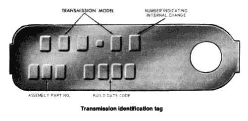
An identification tag is located under the
lower front intermediate servo cover bolt. The tag shows the model
prefix and suffix, assembly part numbers, and the built-date code.
PAN REMOVAL AND FLUID DRAINING
Normal maintenance and lubrication requirements do not include
periodic changes of transmission fluid. A change is required only
when it is necessary to replace the transmission fluid. At this time
the converter, oil cooler core, and cooler lines should be
thoroughly flushed out to remove any dirt or deposits that might
clog these units later.
When filling a completely dry (no fluid) transmission and converter, install five quarts of transmission fluid and then start the engine. Shift the selector lever through all positions briefly and set at Park position. Check the fluid level and add enough fluid to raise the level to between the marks on the dipstick. Do not overfill the transmission.
The procedure for a partial drain and refill of the transmission fluid is as follows:
- Raise the car on a hoist or jack stands.
- Place a drain pan under the transmission pan.
NOTE: On PEA and PEF models (see identification tag), the fluid is drained by disconnecting the filler tube from the transmission fluid pan. - Loosen the pan attaching bolts to allow the fluid to drain.
- When the fluid has stopped draining to level of the pan flange, remove the pan bolts starting at the rear and along both sides of the pan, allowing the pan to drop and drain gradually.
- When all the transmission fluid has drained, remove the pan and the fluid filter and clean them.
- After completing the transmission
repairs or adjustments, install the fluid filter screen, a new pan
gasket, and the pan on the transmission. Tighten the pan attaching
bolts to 12-16 ft. lbs.
NOTE: Be sure to use Type "F" transmission fluid. The use of any /other type of fluid such as Type "A" suffix "A," or DEXRON will materially affect the service life of the transmission. - Install three quarts of transmission fluid through the filler tube. If the filler tube was removed to drain the transmission, install the filler tube using a new O-ring.
- Start and run the engine for a few minutes at low idle speed and then at the fast idle speed (about 1200 rpm) until the normal operating temperature is reached. Do not race the engine.
- Move the selector lever through all positions and place it at the Park position. Check the fluid level, and add fluid until the level is between the "add" and "full" marks on the dipstick. Do not overfill the transmission.
BAND ADJUSTMENT
Intermediate Band
- Clean all the dirt from the band adjusting screw area. Remove and discard the locknut.
- Install a new locknut on the adjusting screw. With the tool shown in the illustration, tighten the adjusting screw until the tool handle clicks. The tool is a pre-set torque wrench which clicks and breaks when the torque on the adjusting screw reaches 10 ft. lbs.
- Back off the adjusting screw exactly 1-3/4 full turns.
- Hold the adjusting screw from turning and torque the locknut to 35-45 ft. lbs.
![]()
Adjusting intermediate band
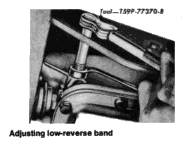
Low-Reverse
Band
- Clean all dirt from around the band adjusting screw, and remove and discard the locknut.
- Install a new locknut on the adjusting screw. Using the tool shown in the illustration, tighten die adjusting screw until die wrench clicks and breaks at 10 ft. lbs. torque.
- Back off the adjusting screw exactly 3 full turns.
- Hold the adjusting screw steady and tighten the locknut to 35-45 ft. lbs.
AUTOMATIC SHIFT LINKAGE ADJUSTMENT
Column Shift
- Place the selector lever in the D (Drive) position against the D stop. On 1970 Mavericks with the C4S semi-automatic transmission, place the selector in the Hi position.
- Loosen the shift rod adjusting nut at point A as shown in the illustration.
- Shift the lever at the transmission into the D or Hi position, third detent from the rear on 1970-71 cars and second detent from the rear on 1972-77 cars.
- Make sure the selector lever on the steering column has not moved from the D or Hi position, then tighten the nut at point A to 10-20 ft. lbs.
- Start the car and check the operation of the selector lever in each selector lever position.
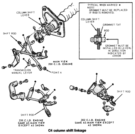
- Place the transmission selector lever in the D (Drive) position against the rearward D stop.
- Raise the vehicle and install jack stands beneath the lower control arms. Move the lever on the transmission to the D position, third detent from the back of the transmission on 1971 models, and second detent from the rear on 1972-77 models.
- With both the selector lever and transmission lever in the D position, torque the attaching nut to 10-20 ft. lbs.
- Start the car and check the operation of the transmission in each selector lever position.
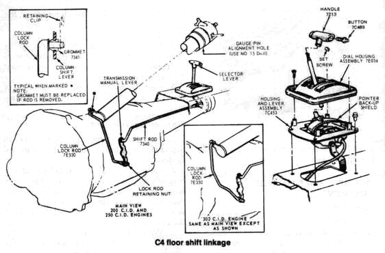
LOCK ROD ADJUSTMENT
Floor or Console
Shift Only
- Adjust the shift linkage as outlined under "Automatic Shift Linkage Adjustment."
- Raise the vehicle and install jack stands beneath the lower control arms. Loosen the lockrod retaining nut.
- Remove the jack stands and lower the vehicle. Place the selector lever in the D position, tightly against the D stop.
- Align the hole in the steering column socket casting with the column alignment mark and insert a 0.180 in. diameter pin (no. 15 drill). The column casting must not rotate with the gauge pin in position.
- Raise the vehicle and reinstall the jack stands. Torque the lockrod retaining nut to 10-20 ft. lbs.
- Remove the jack stands and lower the vehicle. Remove the gauge pin and check the linkage for proper operation.