Maverick and Comet Repair
Chassis Electrical
Ignition Switch
REMOVAL AND INSTALLATION
- Disconnect the negative battery cable.
- Remove the shrouding from the steering column, and detach and lower the steering column from the brake support bracket.
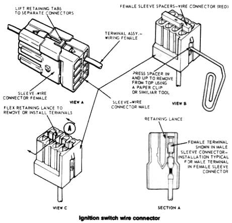
- Disconnect the switch wiring at the multiple plug.
- Remove the two nuts that retain the switch to steering column.
- On models with a steering column mounted gearshift lever, disconnect the ignition switch plunger from the ignition switch actuator rod and remove the ignition switch. On models with a floor mounted gearshift lever, remove the pin that connects the switch plunger to the switch actuator and remove the switch.
- To re-install the switch, place both locking mechanism at the top of the column and the switch itself in the lock position for correct adjustment. To hold the column in the lock position, place the automatic shift lever in PARK or the manual shift lever in Reverse, and turn to LOCK and remove the key. New switches are held in lock by plastic shipping pins. To pin existing switches, pull the switch plunger out as far as it will go and push it back in to the first detent. Insert a 3/32 in. diameter wire into the locking hole in the top of the switch.
- Connect the switch plunger to the switch actuator rod.
8. Position the switch on the column and install the attaching nuts. Do not tighten them.
Headlight Switch
REMOVAL AND INSTALLATION
- Disconnect the negative battery cable.
- Remove the headlight switch control knob and shaft after depressing the release button on the rear of the switch. Some models require special procedures to gain access to the release button. They are: On Mavericks and Comets equipped with air conditioning, disconnect the left A/C duct from the duct-to-register connector, loosen the two nuts that retain the left register to the utility shelf and remove the connector from the register.
- After pulling the switch shaft and knob from the switch, remove the bezel nut that attaches the switch to the instrument panel.
- Lower the switch and disconnect the lead wires from the switch.
- Reverse the above procedure to install the new switch. When installing the new switch, insert the control knob and shaft into the switch until a distinct click is heard, signifying that the shaft is locked in place.
Back-Up Light Switch
REMOVAL AND INSTALLATION
NOTE: Check the condition
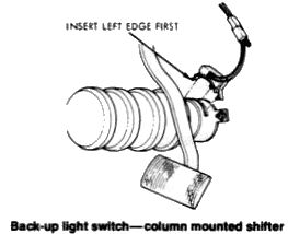
of the bulbs and wiring before replacing the switch. Column Mounted
3-Speed Manual Transmission The switch is mounted at the lower end
of the steering column inside the vehicle.
- To remove the switch, remove the wiring retaining clip (one screw) from the brake pedal support extension.
- Disengage the switch wiring from the clip and disconnect at the plug connector.
- Remove the switch from the steering column (two retaining screws).
- To install the switch, route the wiring from behind the back face of the clip and around through the clip jaws.
- Mount the clip and wiring to the brake pedal support extension.
- Firmly apply the parking brake and depress the clutch. Have a friend observe the operation of the back-up lights when you place the gearshift in Reverse.
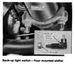
Floor Mounted 3-Speed Manual Transmission
The switch is located under the vehicle at
the rear end of the transmission.
- Place shift control lever in
Neutral and raise vehicle.
CAUTION: Do not get under vehicle without safety stands. Allow exhaust pipes to cool before starting replacement of switch. - Disconnect the electrical connector from the switch.
- Pull the switch from the bracket by slightly rotating in both directions. Be sure that the switch retainer is removed from the switch.
- Set new switch retainer in the bracket.
- Thread the new switch through the hole in the rubber boot. Set the switch into the retainer as far as possible without forcing it.
- Connect the electrical connector to the new switch.
- Firmly apply the parking brake and depress the clutch. Have a friend observe the operation of the back-up lights when you place the shifter in Reverse.
Stoplight Switch
REMOVAL AND INSTALLATION
NOTE: Check the condition of
the bulbs before replacing the switch.
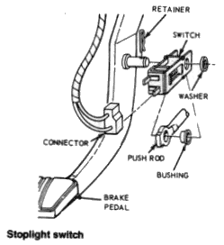
- Disconnect the wires at the connector as shown in the illustration.
- Using pliers, remove the hairpin retainer.
- Slide the stop light switch, the push rod, and the nylon washers and bushing away from the pedal to the right; remove switch in an upward direction.
- To install the switch, position the switch, pushrod, and bushing and washers on the brake pedal pin and press the hairpin retainer into place.
- Connect the wires at the connector.
- Check operation of the switch.
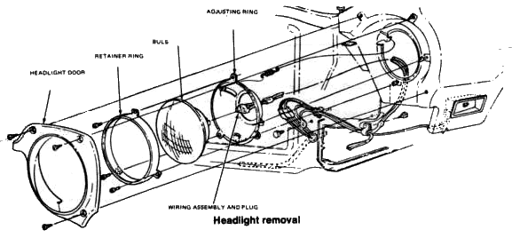
HEADLIGHTS
REMOVAL AND INSTALLATION
- 1. Remove the 3 phillips head screws retaining the headlight door to the fender.
- Loosen, but do not remove, the 3 screws holding the headlight retainer ring.
- While supporting the sealed beam with one hand, rotate the retainer ring counterclockwise until the oversized holes in the ring align with the holding screws.
- Lift the light from the housing.
- Pull the 3-pronged electrical connector from the base of the old light and attach it to the new one.
- Install the new light in the housing. While holding the light in position, rotate the retainer ring clockwise and then tighten the holding screws.
- Check the operation of the headlight.
- Align the locating tab on the bottom of the headlight door with the headlight housing. Install the 3 headlight door retaining screws.