Maverick and Comet Repair
Heating System
w/ Air Condition
DESCRIPTION AND OPERATION
AIR FLOW
Either outside air from the cowl intake or recirculated air from
inside the car enters the right duct of the heater-A/C assembly
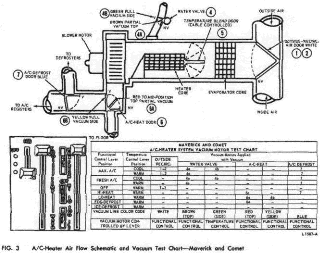
(Fig. 3). The blower motor and wheel draws the air from the right
duct of the heater-A/C assembly through the evaporator core, through
and/or around the heater core into the blower housing and then
forces it into the plenum chamber. From the plenum chamber, the air
discharges through the floor, register, or defroster outlets.
CONTROL OPERATION
The
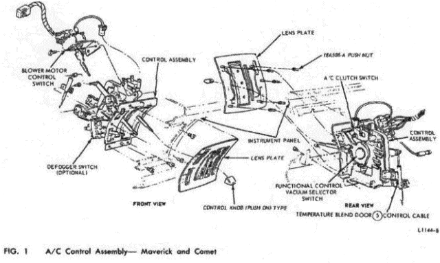
functional (right) control lever on the control head (Fig. 1)
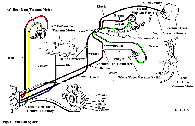
operates the vacuum selector valve which receives vacuum from the
vacuum supply tank and .connects it to four vacuum motors (Fig. 2).
The vacuum motors actuate the outside-recirc (1) (2) door, the
heater water valve (4) (partially) the A/C-Heat door (6) and the
A/C-defrost door (7).
The temperature (center) control lever (Fig. 1) is connected by a cable to a crank arm on the temperature blend (5) door (Fig. 2) which routes the air through and/or around the heater core. The movement of the crank arm also actuates the water valve vacuum switch plunger as shown in Fig. 2. This switch sends additional vacuum to the (4) motor to completely close the water valve.
Also mounted on the control head is a four-position blower switch 4operated by the switch (left) lever, and the A/C compressor clutch switch which is actuated by a cam on the vacuum selector valve (Fig. 1).
COOLING
In both MAX and
FRESH A/C positions of the functional control lever, the cam on the
vacuum selector valve closes the clutch switch (Fig. 1) to engage
the compressor clutch. With the clutch engaged, the compressor pumps
refrigerant through the evaporator core for cooling. The selector
valve also sends vacuum to the top of the water valve motor (4a)
which partially closes the valve (Figs. 2 and 3). If at the same
time the temperature control lever is set at COOL, it actuates the
water valve vacuum switch to send additional vacuum to the motor
(4b) and completely close the valve. With the water valve closed,
there is no water flow through the heater core. If the temperature
lever is set at WARM, the water valve vacuum switch shuts off the
additional vacuum (4b) leaving the water valve partially open. There
is now a partial flow of hot water through the heater core which
modulates the temperature of the cool air from the evaporator.
In MAX A/C position, the (1) (2) door is closed to outside air (vacuum), allowing inside air to recirculate in the system (Fig. 3). In FRESH A/C position (no vacuum), outside air is drawn into the system. In both A/C positions, the air is cooled as it passes through the evaporator core; and then, with the (6) door closed to the floor (no vacuum) and the (7) door closed to the defrosters (vacuum), the cool air discharges through the A/C registers.
HEATING
In OFF,
HI-HEAT, LO-HEAT, FOG-DEFROST, and ICE-DEFROST positions of the
functional control lever, the cam on the vacuum selector valve is
disengaged from the A/C clutch switch (Fig. 1) leaving the switch
open. With the switch open, the compressor is not pumping
refrigerant through the evaporator (no cooling). Also there is no
vacuum to close the water valve (4). With the water valve wide open
(Fig. 3), there is full flow of hot water through the heater core.
In HI-HEAT position, the (1) (2) door (Fig. 3) is open to outside air (no vacuum) and, depending upon the setting of the temperature blend (5) door, the air is drawn through and/or around the heater core into the blower housing. Then, with the (6) door in mid-position (partial vacuum) and the (7) door closed to the defrosters (vacuum), the blower discharges the air through the floor outlet and the A/C registers.
In LO-HEAT position, the system operates in the same manner as in HI-HEAT except that the (6) door is closed to the A/C registers and defrosters (full vacuum) allowing all the air to discharge through the floor outlet.
When the functional control lever is set in FOG-DEFROST position, the system operates in the same manner as in HI-HEAT except that the (7) door is open to the defrosters (no -vacuum). Half the air discharges to the windshield, and half to the floor area.
In ICE-DEFROST position the (1) (2) door is open to outside air (no vacuum), the (6) door is closed to the floor outlets (no -vacuum) and the (7) door is closed to the A/C registers and open to the defrosters (no vacuum). All the air discharges through the defroster nozzles to the windshield.
VACUUM CONTROL SYSTEM OPERATION
The test chart in Fig. 3 will determine which vacuum motors should
be functioning with applied vacuum during the various control lever
positions. Check for proper operation by following the chart and
testing the system as follows:
1. Connect a vacuum gauge in the
vacuum supply (black) Vine between the check valve and the vacuum
selector valve (Fig. 2).
2. Move the functional control lever to
the last position listed (ICE-DEFROST) on the test chart in Fig. 3.
Set the temperature control to WARM.
3. Start the. engine and let
it run until it is warm and a good vacuum reading shows on the
gauge. Turn the key quickly to the ACCESSORY position and observe
the gauge to see if vacuum is maintained or lost. The last control
position listed on the chart (Fig. 3) indicates that no vacuum
should be applied to any of the motors. Therefore, if the gauge
shows a vacuum loss, there is a leak in the vacuum supply (black)
line or at the check valve. If the vacuum reading is maintained, the
system is OK up to the selector valve (Fig, 2). To isolate the
problem, move up to the next position listed on the chart (Fig. 3).
4. For the next position, move the functional control lever up to
FOG-DEFROST and leave the temperature control lever at WARM. Start
the engine again, turn the key quickly to the ACCESSORY position,
and watch the gauge. This position on the chart in Fig. 3 indicates
that vacuum should be applied through the red line only (6A) to the
A/C-Heat door motor.
If the vacuum reading is maintained, there are no leaks in the red line or the top part of the motor. Move the lever up to the next position on the chart and check the (6b) yellow fine by repeating the test.
If the gauge indicates a vacuum loss, there is a leak in the red line or the top part of the motor. Make the repairs or replacements necessary to correct the vacuum leak before moving up to the next position.
5. Continue this test procedure up through
all the control positions to determine the motor or motors causing
the problem. Make the
necessary repairs or replacements to
correct the vacuum leak.
6. If no vacuum leaks are indicated1
throughout ill the control positions, check the motor or door that
could be causing the complaint. for example: Air discharges from the
floor outlet and from the defrosters, but no air comes out o f the
registers when the functional control lever is in HI-HEAT position.
Reference to the schematic in Fig. 3 would indicate that the
A/C-defrost door (7) is closed to the A/C registers and open to the
defrosters (no vacuum). In HI-HEAT, vacuum should be applied to the
(7) motor for the purpose of opening the door to the registers and
closing it to the defrosters.
Disconnect the (blue) vacuum line at the No. (7) door vacuum motor (Fig, 2) and connect it to a vacuum gauge. Again, check the vacuum reading (lever at HI-HEAT) by starting the engine, building up a vacuum, and quickly turning the key to ACCESSORY position. A zero vacuum reading indicates that the line to the motor is plugged or kinked. If vacuum is indicated, either the door is restricted or the motor should be replaced.
ADJUSTMENTS
TEMPERATURE CONTROL
CABLE
Move the temperature control (lower) lever (Fig.
1) to the full up and to the full down positions.
If the lever does not contact either end of the slot, tighten the retaining screw on the cable mounting clip near the temperature door crank arm on the evaporator assembly.
If the lever contacts the upper end of the slot only, loosen the retaining screw and pull the cable down until the lever no longer contacts the upper end of the slot in the full up position, Tighten the retaining screw.
If the lever contacts the lower end of the slot only, loosen the retaining screw and pull the cable up until the lever no longer contacts the lower end of the slot in full down position. Tighten the retaining screw.
HEATER WATER VALVE VACUUM SWITCH
First make sure that the temperature control cable is properly
adjusted as given in the foregoing procedure. Then, move the
temperature control lever to the full COOL (UP) position. If the
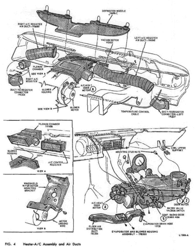
plunger on the water valve vacuum switch (Fig. 4) is not fully
depressed, loosen the adjusting screws and move the switch against
the (5) door crank arm until the plunger is fully depressed. Tighten
the adjusting screws.
If moving the vacuum switch as far as possible against the crank arm will not fully depress the plunger, readjust the temperature control cable.
VACUUM MOTORS
The (1) (2)
motor and the {7) motor are adjustable. The (4) and (6) motors are
not adjustable.
A motor can be adjusted by means of an
adjusting screw Aid slot on the two-piece actuating shaft assembly.
The door operated by the motor must be in its NV (no vacuum applied)
position (Fig. 3).
1. Loosen the adjusting screw.
2. Hold the
air door in its NV position, and adjust the shaft so that the
preload indicator notch is flush with the motor body.
3. Tighten
the adjusting screw.
REMOVAL AND INSTALLATION
CONTROL
ASSEMBLY
To remove the control assembly, remove the
instrument cluster. Pull the knobs off the control levers, blower
switch and defogger switch (Fig. 1). Carefully remove the face plate
by prying it off at the top and bottom alternately. If this is not
done, the mounting pins may be broken. Pry off the lens plate from
the control assembly, then remove the screws retaining the control
assembly to the instrument panel. Move the control assembly out
through the cluster opening and disconnect the vacuum harness
multiple connector, the blower switch and clutch switch wiring and
the control cable. Remove the assembly.
When installing the control assembly, be sure to adjust the control cables. When installing the face plate, position all of the levers between the top of their slots and mid position. Position the plate so that the five pins line up with the elongated holes in the casting. Press evenly on the plate top, center and bottom until all five pins are fully engaged.
BLOWER SWITCH
Remove the
control assembly from the instrument panel as outlined in the
foregoing procedure. Disconnect the wires, remove the retaining
screws and remove the switch from the control assembly (Fig. 1).
CLUTCH SWITCH
Remove the
instrument cluster assembly (Part 33-50), from the vehicle. Working
through the cluster opening, disconnect the clutch switch connectors
and remove the 2 nuts retaining the clutch switch to the control
assembly and remove the switch (Fig. 1).
HEATER-AIR CONDITIONER ASSEMBLY
On the engine side of the dash panel perform the following steps:
1. Disconnect the battery and remove the air cleaner.
2. Drain
the cooling system.
3. Connect a manifold gauge set to the
compressor, and discharge the system.
4. Disconnect the
evaporator core
tubes from the expansion valve, and apply tape
over the core tubes to keep out foreign material. Disconnect the
heater hoses from the heater core tubes.
5. Remove the three A/C
assembly-to-dash pane] mounting stud nuts (Fig. 4). Working at the
passenger side of the dash panel, continue as. follows:
6. To
provide clearance for removing the assembly: remove the utility
shelf from the lower edge of the instrument panel (5 retaining
bolts); remove the right cowl trim panel and utility shelf bracket,
and remove the, radio assembly.
7. Disconnect the right and left
A/C register air ducts from the plenum chamber (Fig. 4).
8.
Remove the floor distribution duct from the blower housing.
9.
Remove the center register from the instrument panel (2 screws) for
clearance. Then pull the plenum chamber part way through the
register opening to disengage it from the blower housing. Disconnect
the (blue) hose from the (7) door motor on the plenum chamber.
10. Disconnect the red .and yellow vacuum hoses from the (6) door
motor and the white hose from the (1) (2) door motor (Figs.. 2 and
4.
11. Disconnect the vacuum harness multiple connector from the
vacuum selector valve on the control assembly.
12. Disconnect the
temperature control cable from the (5) door crank arm on the
evaporator housing, and disconnect the purple and green vacuum hoses
from the adjacent water valve vacuum switch (Figs. 2 and 4).
13.
Remove the screw that retains the evaporator housing to the cowl
upper support, and remove the A/C assembly rearward and away from
the dash panel in order to clear the mounting studs.
14. Remove,
any vacuum hose retaining tape, and disengage any hoses that may be
held by retaining clips.
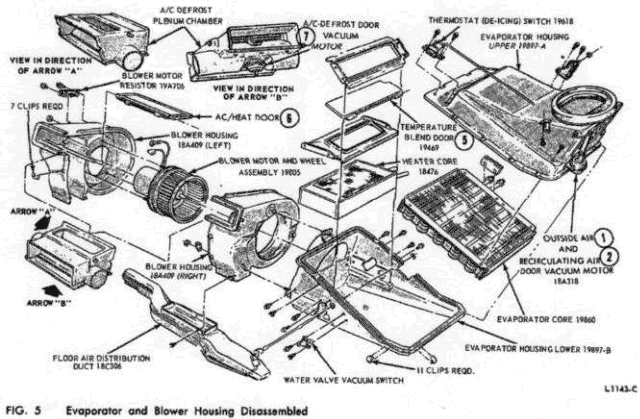
15. Disconnect the wire connectors from
the A/C thermostat (de-icing) switch on the evaporator housing and
from the resistor on the blower housing (Fig. 5). Disconnect the
blower motor ground wire from the windshield wiper motor mounting
bracket.
16. Pull the drain tube from the hole in the floor pan.
17. Lower the evaporator and blower housing assembly and remove it
from the vehicle.
18. When installing the assembly be sure to
connect the vacuum hoses according to the color codes as indicated
in Fig. 2. When connecting to the water valve vacuum switch, connect
the purple hose to the nipple closest to the switch plunger. The
green hose leads, to the water valve motor,
19. After the
assembly is installed, adjust the temperature control cable and, if
necessary, the water valve vacuum switch as outlined in Section 3 of
this part.
20. Evacuate and charge the refrigerant system with
Refrigerant-12.
EVAPORATOR CORE
1. Remove
the heater-air conditioner assembly from the vehicle as outlined in
the foregoing procedure, and place it on a bench.
2. Remove the
flange clips from the housing assembly and separate the upper half
of the housing from the lower half (Fig. 5).
3. Remove the
thermostatic (de-icing) switch retaining screws, and remove the
switch, sliding the capillary tube out of the hole in the evaporator
housing (upper half).
4. Remove the core retaining screws and
remove the evaporator core from the upper half of the housing.
5.
Remove the rubber seal from the evaporator core tubes. Transfer the
seal and the core pads to the new unit.
6. After installing the
new core, install the housing assembly in the vehicle. Leak-test,
evacuate and charge the refrigeration system.
HEATER CORE
J. Remove the
heater-air conditioner assembly from the vehicle as outlined in this
section, and place it on a bench.
2. Remove the flange clips from
the housing assembly, and separate the upper half of the housing
from the lower half (Fig. 5).
3. Remove the water valve vacuum
switch from the lower half of the housing.
4. Remove the
temperature blend (5) door shaft (screw and retaining clip), and
remove the (5) door upper frame (four screws), the door, and the
door lower frame (four screws) from the lower half of the housing
(Fig. 5).
5. Lift the heater core out of the lower housing.
6.
Before installing a new heater core, transfer the pads from the old
to the new core.
7. After installing the core, install the
housing assembly in the vehicle. Leak-test, evacuate, and charge the
refrigeration system.
THERMOSTATIC (DE-ICING) SWITCH
Removal
1. Disconnect the battery ground cable.
2.
Remove the instrument cluster.
3. Remove the ash receptacle
(three screws), and disconnect light,
4. Remove the left duct
assembly and remove the center register. Then remove the right duct
assembly.
5. Disconnect the vacuum hose from the heat/defrost
door (7) at the plenum. Push the plenum assembly to the left to gain
access to the thermostatic (de-icing) switch.
6. Disconnect the 2
connectors at the switch and remove the two screws retaining the
switch to the top of the evaporator (Fig. 5).
7. Working through
the center grille opening and between the package tray and the
instrument panel, remove the thermostatic (icing) switch and pull
the sensing tube out of the core fins.
Installation
1. Feed the
sensing tube into the core fins. Position the thermostatic (icing)
switch to the evaporator and install the 2 retaining screws. Connect
the 2 connectors.
2. Correctly position the plenum and connect
the right duct assembly. Connect the heat/defrost door (7) vacuum
hose to the plenum.
3. Install the center register assembly and
install the left air duct.
4. Install the ash receptacle
assembly.
5. Install the cluster assembly.
6. Connect the
battery ground cable.
BLOWER HOUSING
The blower
housing can be removed without removing the evaporator housing
assembly.
1. Remove the radio assembly.
2. Remove the utility
shelf (5 retaining bolts), and disconnect the right and left A/C
register air duct assemblies from the plenum chamber.
3. Remove
the floor air distribution duct from the bottom of the blower
housing.
4. Remove the blower housing mounting stud nut and lock
plate.
5. Rotate the blower housing to unlock the slotted tabs on
the blower housing from their lock pins on the evaporator housing
(Fig. 5). There are two tabs and pins. Disconnect the red and yellow
hoses at the (6) vacuum motor on the blower housing. Disconnect the
resistor and ground wires, and remove the blower housing.
BLOWER MOTOR AND WHEEL
1.
Remove the blower housing as outlined in the foregoing procedure.
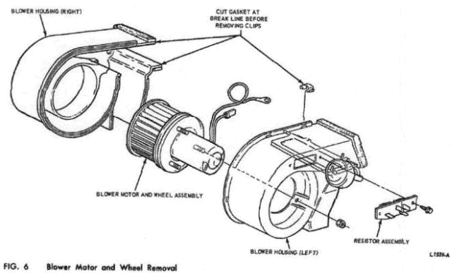
2. Cut the gaskets around the A/C outlets at the break line (Fig.
6).
3. Remove seven clips, and separate the left and right halves
of the blower housing.
4. Remove three blower motor mounting
plate retaining nuts, and remove the motor and wheel assembly from
the housing.
5. When installing, make sure that the A/C-Heat door
is positioned properly before clipping the right and left housings
together.
OUTSIDE/RECIRC (1) (2) AIR DOOR
VACUUM MOTOR
To remove the recirculating door vacuum
motor, remove the 2 nuts retaining the right air register to the
instrument panel utility shelf. Then remove the inboard bolt from
the right instrument pane] bracket and remove the register assembly.
Mark the position of the motor arm and remove the screw connecting
the arm to the motor (Fig. 2). Disconnect the vacuum hose from the
motor, then remove the 2 screws securing the motor to the bracket
and remove the motor.
AC/HEAT DOOR (6) VACUUM MOTOR
To remove the motor, first disconnect the battery ground cable.
Remove the radio assembly (Part 35-01, Section 4). Disconnect the 2
vacuum hoses from the vacuum motor, and remove the hose retaining
clip. Remove the two nuts retaining the motor to the mounting
bracket on the blower housing, and remove the motor (Fig. 2).
HEAT/DEFROST DOOR (7) VACUUM MOTOR
Removal
1. Disconnect the battery ground cable.
2.
Remove the radio assembly (Part 35-01, Section 4).
3. Remove the
2 screws retaining the center register assembly to the instrument
panel and remove the register.
4. Remove-the ash receptacle,
5. Disconnect the left and right duct assemblies from the plenum
chamber.
'«. Remove the utility shelf by removing the 5 retaining
bolts.
7. Disconnect the left and right air ducts from the
outside registers.
8. Disconnect the vacuum hose from the blower
housing.
9. Remove the floor distribution duct from the blower
housing.
10. Remove the lower stud nut and lock plate retaining
the blower motor to the evaporator housing. Rotate the blower motor
to disengage it from the evaporator. Lower the blower motor to the
floor.
11. Remove the A/C-defrost plenum chamber. Then remove the
retaining clip and open the door in the duct (Fig. 1).
12. Remove
the 2 nuts retaining the vacuum motor to the plenum chamber and
remove motor.
Installation
1. Position
the vacuum motor on the A/C-defrost plenum chamber and install the
two retaining nuts and clip.
2. Position the plenum chamber under
the instrument panel, then position the blower motor on the
evaporator housing. Rotate the blower motor to lock it in place on
the evaporator housing. Install the blower housing mounting stud nut
and lock plate.
3. Connect the vacuum hoses to the blower motor
housing and to the heat/defrost door (7) vacuum motor.
4. Install
the center register assembly.
5. Connect the left and right air
ducts to the center register assembly.
6. Install the ash
Receptacle.
7. Install the floor distribution duct on the blower
assembly.
3. Install the package tray and connect the ducts to
the registers at the ends of the instrument panel.
9. Install the
ignition on switch to package tray.
10. Install the radio
assembly.
11. Connect the battery ground cable.
CONDENSER
1. Discharge
the system, and remove both grille upper supports.
2. Remove the
hood latch and support assembly.
3. Disconnect the evaporator-
to-condenser hose at the receiver tank.
4. Disconnect the
compressor-to-condenser hose at the condenser, and remove the clip
holding the hoses together at the radiator support.
5. Remove the
bolts attaching the condenser to the radiator front support, and
remove the condenser.
6. Transfer the receiver tank to the new
condenser. .
7. Position the condenser to the radiator support,
and install the attaching bolts.
8. Connect the
evaporator-to-receiver tank hose, and connect the
compressor-to-condenser hose.
9. Install the hood latch and
support, and install both grille upper supports.
10. Install the
clip holding the hoses together at the radiator support.
11. Leak
test, evacuate and charge the system.
MAVERICK AND COMET HEATER-AIR
CONDITIONER SPECIFICATIONS
Blower Motor current Draw
at 12.8 Volts....... 16A to 20 Amps on High Blower
Refrigerant
Charge.........1-7/8 pounds
Protection Device...30 Amp Fuse in
Fuse Panel
Control Illumination....2 CP No. 1895 Bulb
Magnetic
Clutch Current Draw.....3.75 Amps. Max.