Maverick and Comet Repair
Maverick and Comet Brakes
BRAKE SYSTEM
Self-adjusting, internal expanding duo-servo drum brakes are
standard equipment on all 1970-75 Maverick and Comets. Sliding
caliper front disc brakes are available as optional equipment on
1974-75 models and standard on 1976-77 models. Power assist is used
on disc brake models.
DRUM BRAKES
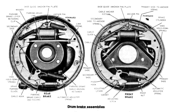
Drum brakes on all Mavericks and Comets employ single-anchor,
internal-expanding, and self-adjusting brake assemblies. The
automatic adjuster continuously maintains correct operating
clearance between the linings and the drums by adjusting the brake
in small increments in direct proportion to lining wear. When
applying the brakes while backing up, the linings tend to follow the
rotating drum counterclockwise, thus forcing the upper end of the
primary shoe against the anchor pin. Simultaneously, the wheel
cylinder pushes the upper end of the secondary shoe and cable guide
outward, away from the anchor pin. This movement of the secondary
shoe causes the cable to pull the adjusting lever upward and against
the end of the tooth on the adjusting screw starwheel. As lining
wear increases, the upward travel of the adjusting lever also
increases. When the linings have worn sufficiently to allow the
lever to move upward far enough, it passes over the end of the tooth
and engages it. Upon release of the brakes, the adjusting spring
pulls the adjuster lever downward, turning the star-wheel and
expanding the brakes.
INSPECTION
- Raise the front or rear of the car and support the car with safety stands. Make sure that the parking brake is not on.
- If you are going to check the rear brakes, remove the lug nuts that attach the wheels to the axle shaft and remove the tires and wheels from the car. Using a pair of pliers, remove the tinnerman nuts from the wheel studs. Pull the brake drum off the axle shaft. If the brakes are adjusted too tightly to remove the drum, see Step 4. If you can remove the drum, see Step 5.
- If you are going to check the front brakes, then the front tire, wheel and brake drum can be removed as an assembly. Remove the hub cap, then either pry the dust cover off the spindle with a screwdriver or pull it off with a pair of channel-lock pliers. Remove the cotter pin from the spindle. Slide the nut lock off the adjusting nut, then loosen the adjusting nut until it reaches the end of the spindle. Do not remove the adjusting nut yet. Grab the tire and pull it out toward yourself, then push it back into position. This will free the outer wheel bearing from the drum hub. If the brakes are adjusted up too tightly to allow the drum to be pulled off them, go to Step 4 and loosen up the brakes, then return here. Remove the adjusting nut, washer and outer bearing from the spindle. Pull the tire, wheel, and brake drum off the spindle.
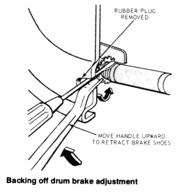
- If the brakes are too tight to remove the drum, get under the car (make sure that you have safety stands under the car to support it) and remove the rubber plug from the bottom of the brake backing plate. Shine a flashlight into the slot in the plate. You will see the top of the adjusting screw starwheel and the adjusting lever for the automatic brake adjusting mechanism. To back off on the adjusting screw, you must first insert a small, thin screwdriver or a piece of firm wire (coat-hanger wire) into the adjusting slot and push the adjusting lever away from the adjusting screw. Then, insert a brake adjusting spoon into the slot and engage the top of the star-wheel. Lift up on the bottom of the adjustment spoon to force the adjusting screw star-wheel downward. Repeat this operation until the brake drum is free of the brake shoes and can be pulled off.
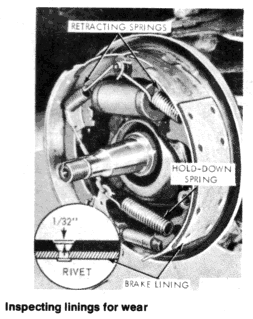
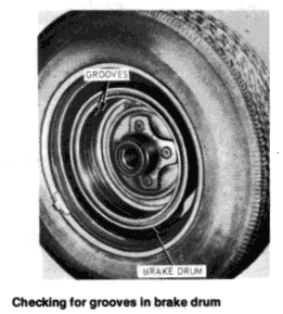
- Clean the brake shoes and the inside of the brake drum. There must be at least 1/16 in. of brake lining above the heads of the brake shoe attaching rivets. The lining should not be cracked or contaminated with grease or brake fluid. If there is grease or brake fluid on the lining, it must be replaced and the source of the leak must be found and corrected. Brake fluid on the lining means leaking wheel cylinders. Grease on the brake lining means a leaking grease retainer (front wheels) or axle seal (rear brakes). If the lining is slightly glazed but otherwise in good condition, it can be cleaned up with medium sandpaper. Lift up the bottom of the wheel cylinder boots and inspect the ends of the wheel cylinders. A small amount of fluid in the end of the cylinders should be considered normal. If fluid runs out of the cylinder when the boots are lifted, however, the wheel cylinder must be rebuilt or replaced. Examine the inside of the brake drum; it should have a smooth, dull finish. If excessive brake shoe wear caused grooves to wear in the drum it must be machined or replaced. If the inside of the drum is slightly glazed, but otherwise good, it can be cleaned up with medium sandpaper.
- If no repairs are required, install the drum and wheel. If the brake adjustment was changed to remove the drum, adjust the brakes until the drum will just fit over the brakes. After the wheel is installed it will be necessary to complete the adjustment. See "Brake Adjustment" later in this chapter. If a front wheel was removed, tighten the wheel bearing adjustment nut to 17-25 ft. lbs. while rotating the wheel. This will seat the bearing. Loosen the adjusting nut 1/2 turn, then retighten it to 10-15 ft. lbs.
BRAKE DRUM REMOVAL
AND INSTALLATION
See Steps 3 and 4 under "Drum Brakes
Inspection."
BRAKE SHOE REMOVAL
AND INSTALLATION
NOTE: If you are not thoroughly
familiar with the procedures involved in brake replacement, only
disassemble and assemble one side at a time, leaving the other wheel
intact as a reference.
- Remove the brake drum. See the inspection procedure.
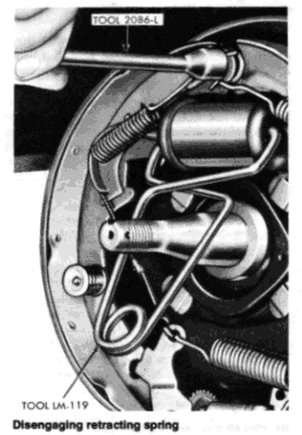
- Place the hollow end of a brake spring
service tool (available at auto parts stores) on the brake shoe
anchor pin and twist it to disengage one of the brake retracting
springs. Repeat this operation to remove the other spring
CAUTION: Be careful the springs do not slip off the tool during removal, as they could cause personal injury. - Reach behind the brake backing plate and place a finger on the end of one of the brake hold-down spring mounting pins. Using a pair of pliers, grasp the washer on the top of the hold-down spring that corresponds to the pin that you are holding. Push down on the pliers and turn them 90° to align the slot in the washer with the head on the spring mounting pin. Remove the spring and washer and repeat this operation on the hold- down spring on the other brake shoe.
- Place the tip of a screwdriver on the top of the brake adjusting screw and move the screwdriver upward to lift up on the brake adjusting lever. When there is enough slack in the automatic adjuster cable, disconnect the loop on the top of the cable from the anchor. Grasp the top of each brake shoe and move it outward to disengage it from the wheel cylinder (and parking brake link on rear wheels). When the brake shoes are clear, lift them from the backing plate. Twist the shoes slightly and the automatic adjuster assembly will disassemble itself.
- If you are working on rear brakes, grasp the end of the brake cable spring with a pair of pliers and, using the brake lever as a fulcrum, pull the end of the spring away from the lever. Disengage the cable from the brake lever.
- The brake shoes are installed as follows: If you are working on the rear brakes, the brake cable must be connected to the secondary brake shoe before the shoe is in¬ stalled on the backing plate. To do this, first transfer the parking brake lever from the old secondary shoe to the new one. This is accomplished by spreading the bottom of the horseshoe clip and disengaging the lever. Position the lever on the new secondary shoe and install the spring washer and the horseshoe clip. Close the bottom of the clip after installing it. Grasp the metal tip of the parking brake cable with a pair of pliers. Position a pair of side cutter pliers on the end of the cable coil spring and, using the pliers as a fulcrum, pull the coil spring back with the side cutters. Position the cable in the parking brake lever.
- Apply a light coating of high-temperature grease to the brake shoe contact points on the backing plate. Position the primary brake shoe on the front of the backing plate and install the hold-down spring and washer over the mounting pin. Install the secondary shoe on the rear of the backing plate.
- If working on the rear brakes, install the parking brake link between the notch in the primary brake shoe and the notch in the parking brake lever.
- Install the automatic adjuster cable loop end on the anchor pin. Make sure that the crimped side of the loop faces the backing plate.
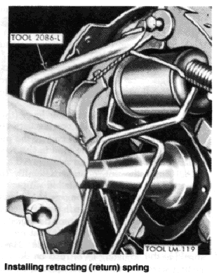
- Install
the return spring in the primary brake shoe and, using the tapered
end of a brake spring service tool, slide the top of
the spring onto the anchor pin.
CAUTION: Be careful to make sure that the spring does not slip off the tool during installation, as it could cause injury. - Install the automatic adjuster cable
guide in the secondary brake shoe, making sure that the flared hole
in the cable guide is
inside the hole in the brake shoe. Fit the cable into the groove in the top of the cable guide. - Install the secondary shoe return spring through the hole in the cable guide and the brake shoe. Using the brake spring tool, slide the top of the spring onto the anchor pin.
- Clean the threads on the adjusting screw and apply a light coating of high-temperature grease to the threads. Screw the adjuster closed, then open it one-half turn.
- Install the adjusting screw between the brake shoes with the starwheel nearest to the secondary shoe. Make sure that the star-wheel is in a position that is accessible from the adjusting slot in the backing plate.
- Install the short hooked end of the automatic adjuster spring in the proper hole in the primary brake shoe.
- Connect the hooked end of the automatic adjuster cable and the free end of the automatic adjuster spring in the slot in the top of the automatic adjuster lever.
- Pull the automatic adjuster lever (the lever will pull the cable and spring
with it) downward and to the left and engage the pivot hook of the
lever in the hole in the secondary brake shoe.
18. Check the entire brake assembly to make sure everything is installed properly. Make sure that the shoes engage the wheel cylinder properly and are flush on the anchor pin. Make sure that the automatic adjuster cable is flush on the anchor pin and in the slot on the back of the cable guide. Make sure that the adjusting lever rests on the adjusting screw starwheel. Pull upward on the adjusting cable until the adjusting lever is free of the starwheel, then release the cable. The adjusting lever should snap back into place on the adjusting screw starwheel and turn the wheel one tooth.
19. Expand the brake adjusting screw until the brake drum will just fit over the brake shoes.
20. Install the wheel and drum and adjust the brakes. See "Brake Adjustment."
DRUM BRAKE ADJUSTMENT
NOTE: Drum, brakes installed in Mavericks and Comets are
self-adjusting. All that is normally required to adjust the brakes
is to apply them moderately hard several times while carefully
backing the car in Reverse. However, if this action proves
unsatisfactory, or if it proves necessary to re-adjust the brakes
after replacing the linings or removing the drum, the following
procedure may be used.
- Raise the car and support it with safety stands.
- Remove the rubber plug from the adjusting slot on the backing plate.
- Insert a brake adjusting spoon into the slot and engage the lowest possible tooth on the starwheel. Move the end of the brake spoon downward to move the starwheel upward and expand the adjusting screw. Repeat this operation until the brakes lock the wheel.
- Insert a small screwdriver or piece of firm wire (coat-hanger wire) into the adjusting slot and push the automatic adjuster lever out and free of the starwheel on the adjusting screw.
- Holding the adjusting lever out of the way, engage the topmost tooth possible on the starwheel with a brake adjusting spoon. Move the end of the adjusting spoon upward to move the adjusting screw starwheel downward and contract the adjusting screw. Back off the adjusting screw starwheel until the wheel spins freely with a minimum of drag. Keep track of the number of turns the star- wheel is backed off.
- Repeat this operation for the other side. When backing off the brakes on the other side, the adjusting lever must be backed off the same number of turns to prevent side-to-side brake pull.
- Repeat this operation on the other set of brakes (front or rear).
- When all 4 brakes are adjusted, make several stops, while backing the car, to equalize all of the wheels.
- Road-test the car.